Veröffentlicht am 22.02.2022 von Eric Kortemeier
Dieses Paper wurde auf Englisch verfasst, der Reichweite halber wird aus auch hier im deutschsprachigen Teil veröffentlicht.
Abstract
During development of the powertrain, engineers face the challenge of designing an electronic control module (ECM) for reliable data processing, so that pilots can monitor and control the drivetrain. In electric aircraft, data to monitor the powertrain must be displayed in the cockpit and pilot control commands have to be processed into motor commands to control the engine. The aircraft battery is supervised by a battery management system (BMS), which collects the battery data and controls the powerlines. This article focuses on BMS integration into the ECM of the FVA 30 hybrid electric motor glider using a Speedgoat real-time target machine.
FVA 30
The aircraft features two electric motors at the tail (Fig. 1). A high voltage lithium-ion battery pack directly behind the canopy provides enough energy for short flights powered exclusively by the battery. The fuselage contains two inverters to supply the engines with AC voltage. As a hybrid electric aircraft, an additional generator and inverter connected to a propulsion engine charges the battery during the flight. This combination of a highly efficient electric powertrain with fuel as an energy source enables long flights with a range of up to 650km. (Fig. 2) [4]
Figure 1: FVA 30 design

Electronic Control Module
In the trial phase, the ECM consists of a Speedgoat Baseline real-time target machine and is programmed with Simulink. This enables rapid testing opportunities through a user-friendly interface. The ECM manages the data acquisition, signal generation and engine control. With 4 CAN Ports the Speedgoat IO614 module ensures robust serial communication managed by the ECM. An additional Speedgoat IO397 module for analog and digital signals offers further possibilities to communicate with sensors and actuators, such as cooling pumps. An important part of the ECM is the communication with the BMS. Safety critical data must be evaluated and the ECM must check the system state of the BMS. In order to monitor the connection, the ECM sends periodic commands via a CAN bus. While the battery contactors are closed, high voltages are applied to the drivetrain of the aircraft to achieve the necessary power requirements. In case of deviations from the recommended values, the ECM should immediately open the battery contactor to maintain safe flight conditions. On the other hand, loss of power during operation endangers the flight conditions. Therefore, oversensitive safety conditions should be avoided. As a solution, an operation management system for the electric powertrain was developed.
Figure 2: FVA 30 factsheet
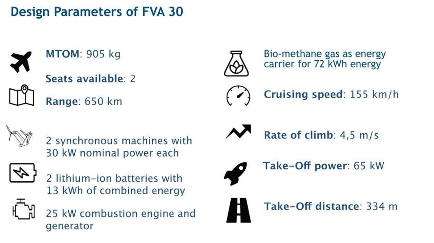
Figure 3: Battery submodule in front of the Speedgoat Baseline real-time target machine
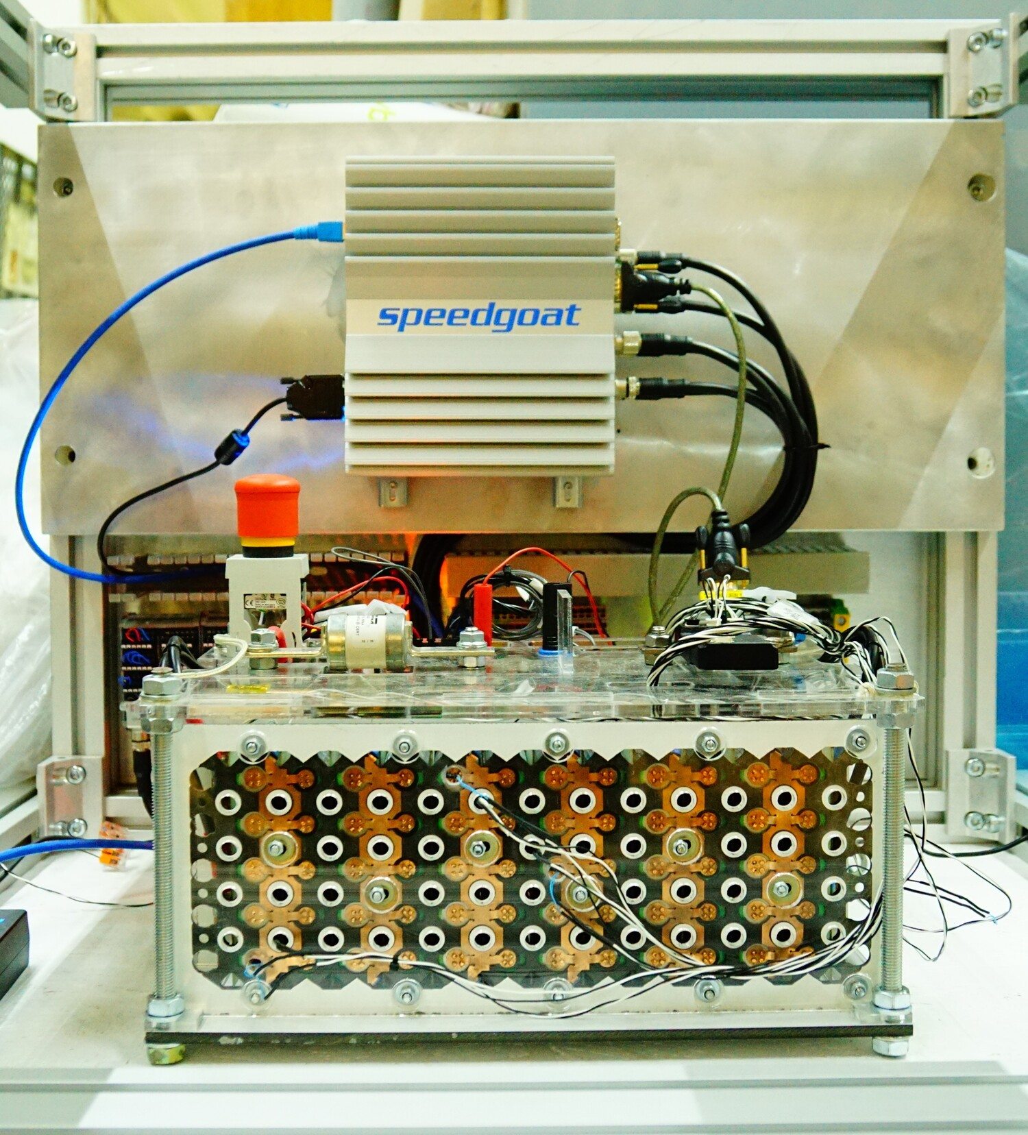
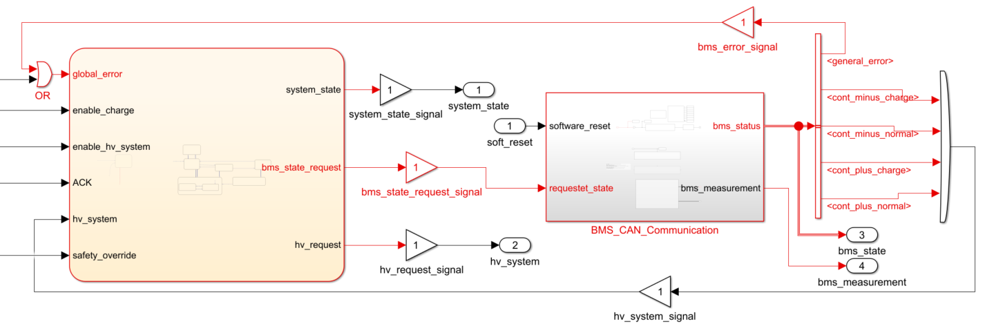
Figure 4: Simulink model of the ECM
Display Unit
The pilot must supervise all relevant data of the drivetrain. For this purpose, the FVA 30-Team is developing a display unit, which will be supplied with information directly from the Speedgoat ECM via CAN communication. The inverter provides data about the rotational speed, the system status and the status of the engine. Data about the actual power, battery voltage and the state of charge (SOC) will be sent by the battery management system. [1]
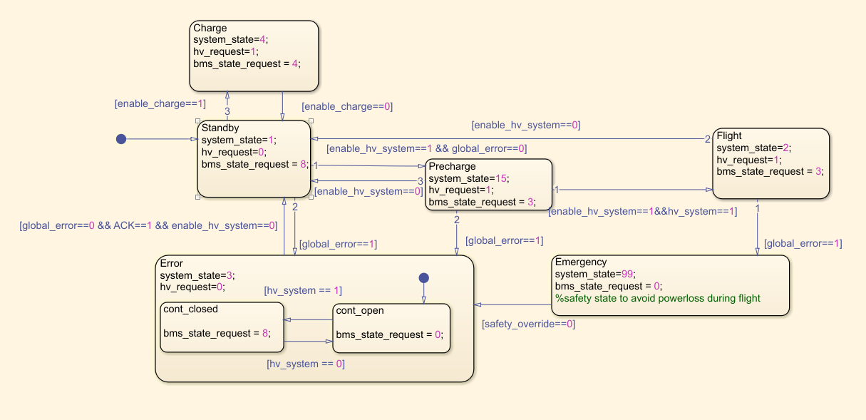
Figure 5: Statemachine for operation managemant of the BMS
Battery Management System
The FVA 30 uses a modular open source BMS development platform called foxBMS developed by the Fraunhofer Institute for Integrated Systems and Device Technology (IISB). The foxBMS builds a state-of-the-art control unit for a lithium-ion battery. The LTC6813-1 multi-cell battery stack monitor measures 12 voltages and 8 temperatures via a negative temperature coefficient thermistor (EPCOS B57861S). A current sensor, a DC fuse and an insulation device, which measures the resistance between the HV-system and the aircraft ground completes the BMS. The current flow out of the high voltage battery is switched on and off by electronic contactors in both plus and minus power lines. Additionally, a pre-charge resistor is connected by a third contactor to restrict inrush currents. Different system states consider the status of the contactors and define the boundaries for temperature, voltage and current. After the software is reset, the BMS starts in the ’uninitialized’ state and switches to the ’idle’ state. When a request is received for the ’standby’ state, the BMS checks all the subsystems and updates its state to ’standby’. A subsequent request for the ’normal’ state will cause the BMS to switch to the ’precharge’ state and the minus and precharge contactor to close. After the precharge process the load voltage equals the battery voltage and the plus contactor is closed. The precharge power line is opened again and the BMS state machine changes to the ’normal’ state. If any cyclic checks of the monitored parameters fail, the BMS assumes the ’error’ state and immediately opens all the contactors. The foxBMS platform includes three safety steps listed below in ascending order of importance.
-
- MOL - Maximum Operating Limit
- RSL - Recommended Safety Limit
- MSL - Maximum Safety Limit
While MOL and RSL violations represent warnings to inform the pilot, a MSL failure will habe an impact on the BMS state machine. For communication with the BMS, a CAN interface is implemented in the foxBMS platform, which offers two functions: request the BMS states, and read the BMS measurement and status information. Fixed CAN identifiers for transmitted and received messages enables a robust serial communication between the BMS and ECM. [2]
Operation management
The operation management of the FVA 30 ECM is structured with a Simulink Stateflow state machine. The functional purpose is to calculate the system state to control the state of the BMS, inverter and motor, based on the data received. The implementation presented in this whitepaper refers only to the BMS and therefore to the switching states of the contactors. Figure 4 shows the Stateflow block on the left and the communication subsystem for the Speedgoat IO614 module on the right. The ’bms state request’ output signal of the ECM state machine is connected to the communication subsystems and sent to the BMS via the CAN bus. The information received from the bus is packed into the ‘bms_status’ output signal from the communication subsystem. This is split into four signals for the contactor states and the ‘general_error’ signal containing BMS error occurrences. Before the error signal is fed back to the statemachine, an additional signal is added by an OR-operator to simulate errors. Also the contactor status signals are captured by an ORoperator and transmitted to the ’hv system’ input of the statemachine. Figure 5 shows the states and transitions of the ECM. In ’Standby’ state the high voltage part of the powertrain is separated. When normal mode is enabled, the ECM assumes the ’Precharge’ state and sends a request to the BMS to close the precharge and minus contactor. If the precharge process is completed the BMS closes the main contactors and sets the system state to ’Flight’. Each system state sets the ’bms state request’ variable to the corresponding request number for the foxBMS displayed in Table 1.
Table 1: Connection between BMS state and request value (Source: Fraunhofer IISB, [3])
| Value | Requested BMS state | Contactors |
|---|---|---|
| 0 | No request | - |
| 3 | Normal | Closed |
| 4 | Charge | Closed |
| 8 | Standby | Open |
In case of errors, the system state assumes the ’cont closed’ substate of the ’Error’ state and requests the BMS to open the contactors. If all the contactors are open, the sub state switches and terminates further requests for the BMS state. Fixing and acknowledging the fault sets the state back to ’Standby’. To meet the challenges stated above, an additional safety state is implemented if the ’Flight’ state switches to the ’Error’ state (see Fig. 5). This prevents powerloss during critical moments of the flight and can be separately enabled or disabled using the input ’safety override’. [4]
Figure 6: Simulink real-time explorer instrument panel
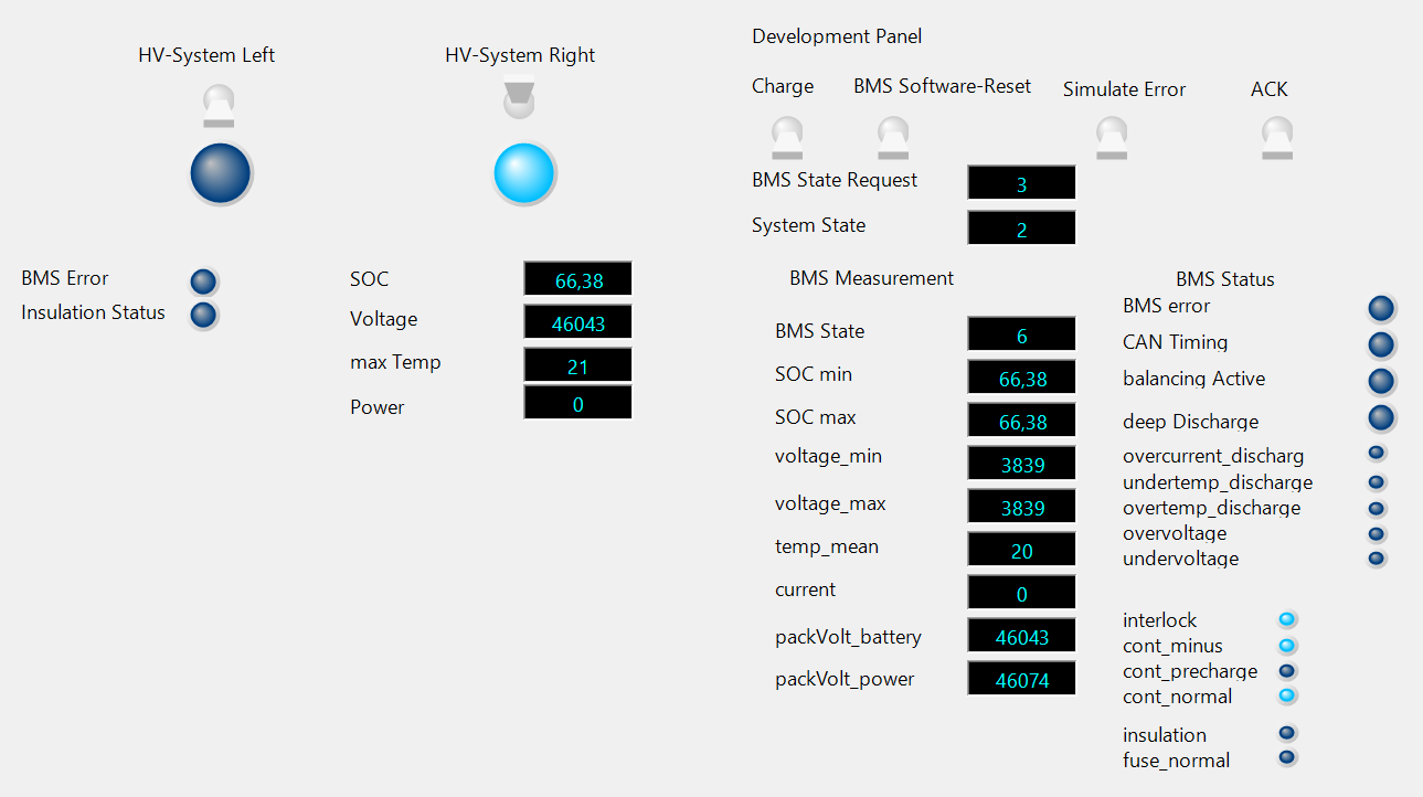
Validation with Simulink RealTime Explorer
Realistic conditions must be achieved to test and validate the functionality of the BMS. While conventional software projects can be tested in a simulation environment on the development PC, for the ECM, fast processing of the data and the interaction of individual communication modules are of prime importance. The validation must therefore be done in real-time directly on the target hardware. The Speedgoat target machine supports fast building and uploads of Simulink models, which enables cyclic checks of individual work steps. This facilitates the software development and prevents bugs. A Simulink Real-Time Explorer Instrument Panel was built (represented in Figure 6) to generate different scenarios for the FVA 30 ECM. Separate user interfaces for the pilot and the developer show the cockpit parameters displayed. With access to internal signals while the model is running on the Speedgoat target machine, the ECM states can all be verified to validate expected system behavior. Fault reactions are also tested by introducing simulated errors into the system.
Conclusion
The battery management system features multiple safety functions and is therefore an important part of the electrical powertrain. Given the stringent demands of the aviation sector, flawless functionality is an absolute must. Consequently, reliable communication between the ECM and the BMS is of the utmost priority. The real-time tests of the control unit for the battery management system showed good interaction of both components and suggest that the ECM presented is reliable for aeronautics applications. Using a Speedgoat real-time target machine an individual module of the aircraft drivetrain was developed and validated. The test bench built can be quickly adapted for upcoming changes and will subsequently be extended to include the FVA 30 inverter and motor.
Software
- Matlab® & Simulink®
- Matlab Coder™
- Simulink Real Time™
- Simulink Coder™
- Simulink Stateflow™
- Speedgoat I/O Blockset
References
- EASA: Special Condition - CS-22 - Installation of electric propulsion units in powered sailplanes: SC-22.2014-01. https://www.easa.europa.eu/downloads/16912/en . Version: 14.11.2014
- Fraunhofer IISB: The foxBMS Documentation. https://iisb-foxbms.iisb.fraunhofer.de/foxbms/gen1/docs/html/latest/ . Version: 31.01.2022
- Fraunhofer IISB: The foxBMS Documentation, 7. Communicating with foxBMS. https://iisb-foxbms.iisb.fraunhofer.de/foxbms/gen1/docs/html/latest/getting_started/communicating/communicating.html . Version: 31.01.2022
- Moxter, T. ; Enders, W. ; Kelm, B. ; Scholjegerdes, M. ; Koch, C. ; Garbade, M. ; Dahmann, P.:Investigation of Alternative Propulsion Concepts for Small Aircraft with the Hybrid Electric Motor Glider FVA 30