Since gliding is very dependent on the weather, good planning is essential before any cross-country flight. However
even the best preparation cannot always protect the pilot from decreasing thermals. This often leads to
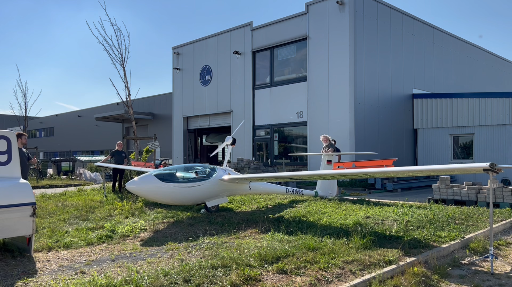
to a so-called out landing. This is exactly where our electric sustainer comes in.
It allows the pilot to avoid an out landing and return safely to the home airfield.
Compared to conventional non-electric sustainers, it offers additional safety, reliability and lower
emissions.
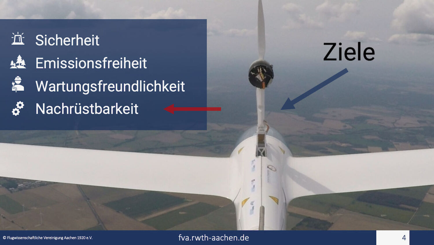
Background and motivation
Conventional sustainers with combustion engines require a high degree of concentration from the pilot during operation
Even minor errors during use or inadequate maintenance can lead to a total failure of the system.
failure. This situation poses a high safety risk, as home-return aids are primarily used at lower altitudes
to enable continued flight despite the lack of thermals. Through the use of an electric powertrain and a simple and intuitive operating concept, the described risks are minimized.
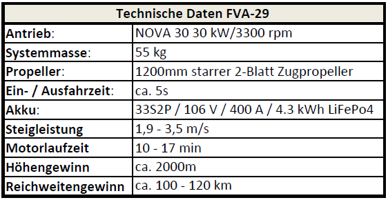
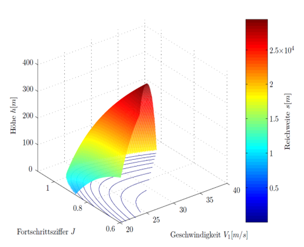
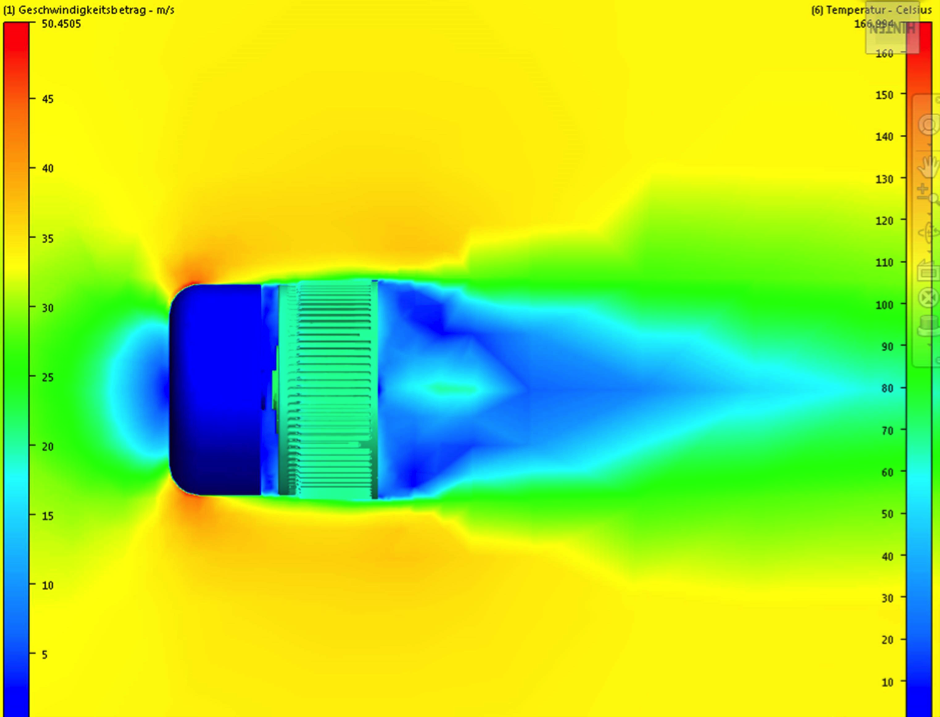
at the same time, the FVA 29 achieves through aerodynamic optimization of the components - especially mast and propeller -
and the explicit design for the required operating point, the FVA 29 achieves an overall efficiency of more than 70%.
This will enable a range of a theoretical 120 km at a climb rate of about 2 m/s.
In addition to making a direct contribution to increasing flight safety, the electric homeward bound aircraft is also expected to provide insights into the
use of electric motors and batteries in small aircraft.
Spin tests to determine the highest flyable yaw rate (torsional load of the
mast)
Preliminary design of the main structural components
2014
2015
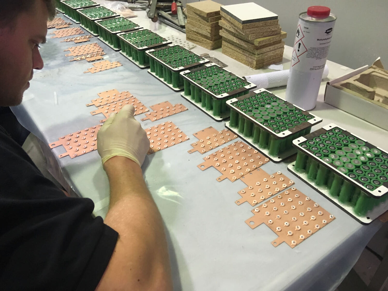
Development of an automated soldering process for the assembly of battery cells
Determination of the optimal cell type (18650 Li-Ion)
Control unit: EAGLE Control Unit (ECU) similar to ASG 32 El and programming by
the Rosenheim University of Applied Sciences
Registration of the project for national approval at the German Federal Aviation Authority (LBA)
Revision of mast kinematics: lightweight FRP construction, change to more stable
mast-airplane connection
Classical bench test of the motor (Plettenberg) at the IEM of the RWTH, setup with load machine,
measuring shaft and test specimen
2016
Production of the propeller forming mould and propeller centering: Improvement of the bonding of the
aluminum hub
with the FRP of the propeller
Flight battery: battery packs, dimensional and geometrical computer model structure and
completion of the
extension kinematics
Fracture and tensile tests of tensile specimens and subsequently of the kinematic parts from
wound fibre rovings
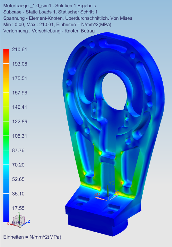
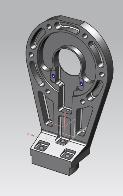
Fabrication and hardening (RWTH IMM) of the aluminum parts (mast base and motor mount)
2017
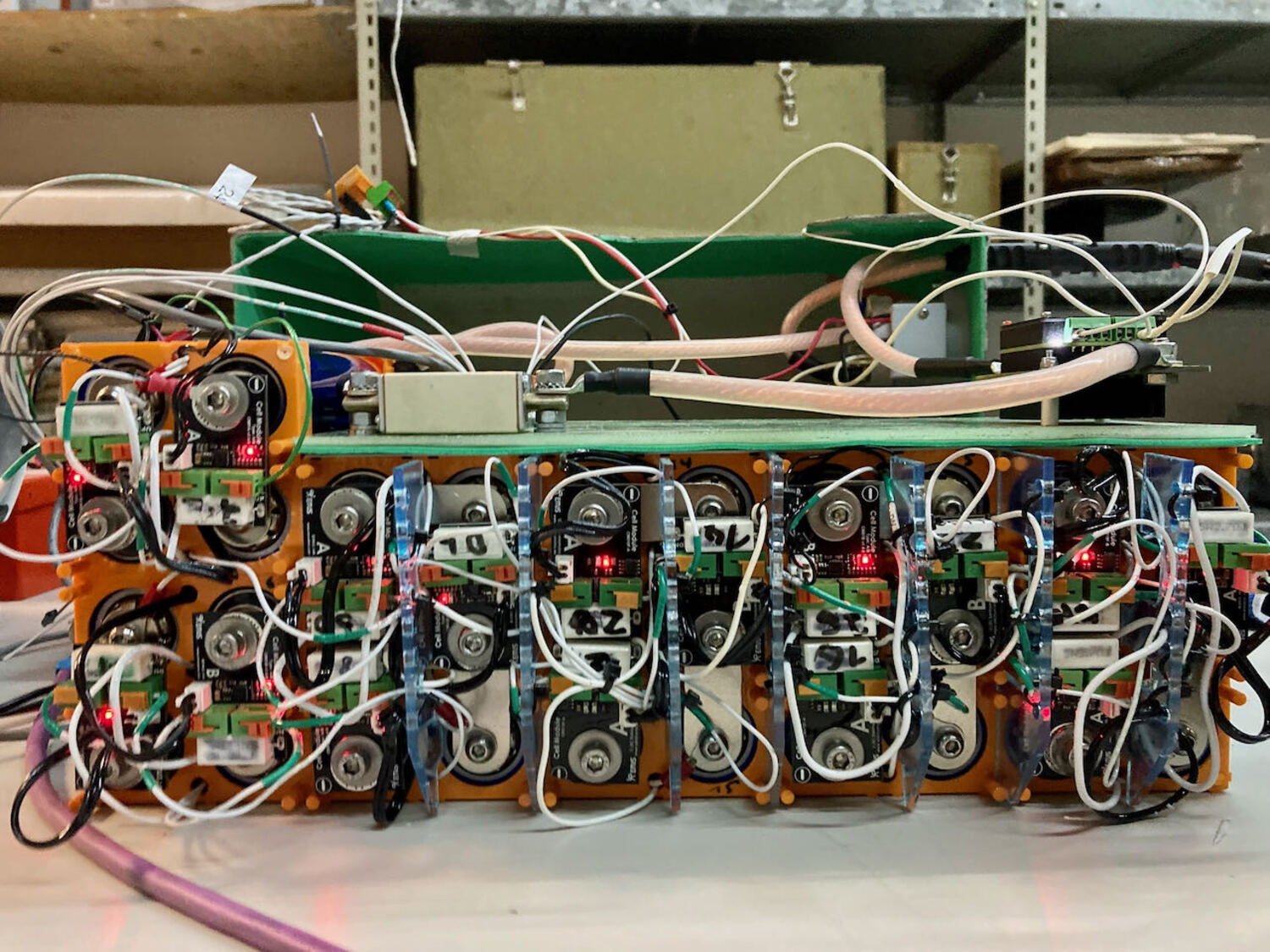
Completion of the laboratory battery (60 cells of the type with a capacity of 2.5 kWh at 96 V
and max. 150 A) for flexible ground testing of the drive system.
Structure Health Monitoring Mast (SHM-Mast): Gluing in the sensors and tests on the
Kinematics Mock-Up
Testing: Propeller test (nominal speed 3300rpm over 50h), required for certification by
the LBA
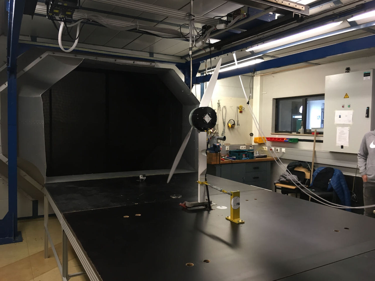
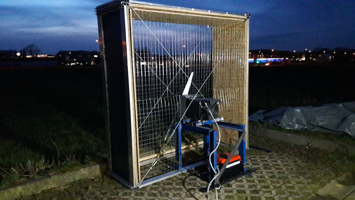
Wind tunnel tests with spare mast but engine and propeller to estimate the
performance values:
Real thrust very good, but braking force of the motor (holding torque) too low.
2018
Integration: Engine Control Unit
Development of an intelligent propeller brake to increase the propeller's
holding torque
to support the engine in the low speed range and to ensure a locking of the propeller in the retracting postion
Integration of the Engine Control Unit (ECU) into the instrument panel and testing
Load test of the predestined first flight mast as well as another wind tunnel test
with the
propeller
2019
Performing on-ground testruns of the FVA 29 powertrain using the lab battery.
First flight test of the system: extension and retraction times of the motor mast in-flight and
Flight characteristics with
Extended mast
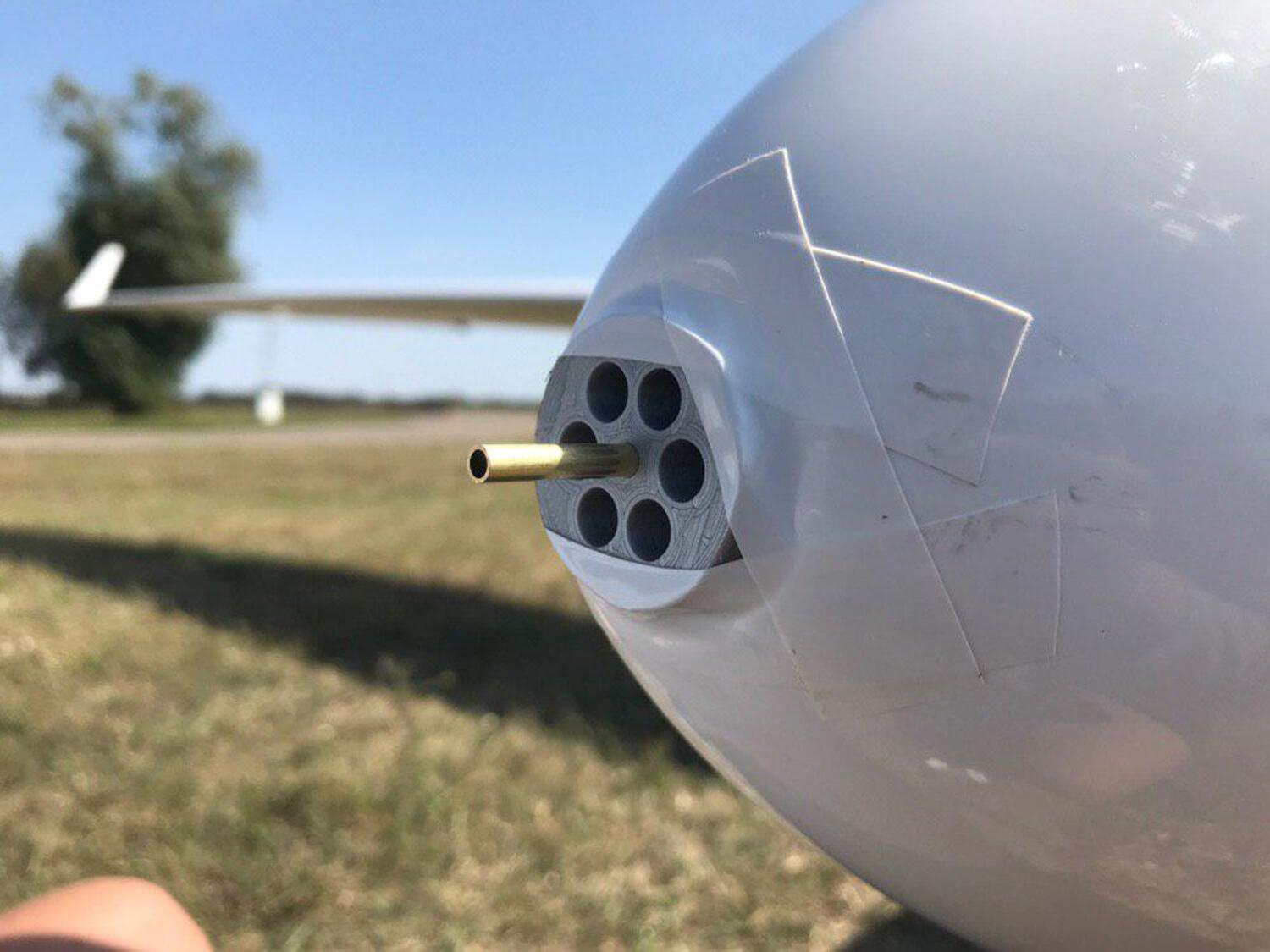
Relocation of the dynamic pressure pitot tube into the aircraft nose due to first extension/retraction tests in the
flight.
Assembly of battery packs according to original design with cells type 18650
by bonding the conductor plates with conductive epoxy adhesive
2020
Problem of detaching conductor sheets: Findings must be obtained through material tests
material tests in order to investigate further use of this connection technology.
Based on the experience: Development and construction of a so-called "transition battery" with the
goal to
the safer LiFePo cell technology and simpler assembly of the Headway cells type
38120
Improvement of the mast mechanics and elimination of problematic areas such as improvement of the
failure safety of the pushbuttons
Extension of flight testing to include tests on windmilling of the propeller and evaluation of
corresponding
descent polars and speeds
2021
Testing of the transition battery for in-flight use: charge and discharge cycles as well as
safety tests
Functional Hazard Assessment (FHA) and System Safety Assessment (SSA) for the electric
powertrain and primarily the traction battery.
Optimization of the kinematics Improvement of the functionality, installation of motor mount S/N 2 with
low
manufacturing distortion as well as correction of the mast, replacement of bushings and screw connections
2022
Ground tests with transition battery installed
Establishment of a test plan for battery certification
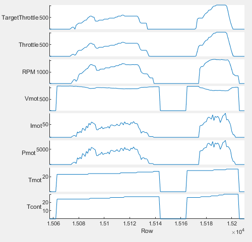
Generation of operational data
Detailed solutions for the integration of the system
Components and approval
In addition to the structural components, the operational reliability of the entire powertrain must be demonstrated.
For this, a battery testing program and a ground testing program have been established. More systems will be tested in stages during the test,
before the full flight test program is finally flown. For example, the successful completion of ground testing enabled
the first exit and entry tests at the idaflieg summer camp. The individual components are listed below, along with the associated verification and required testing.
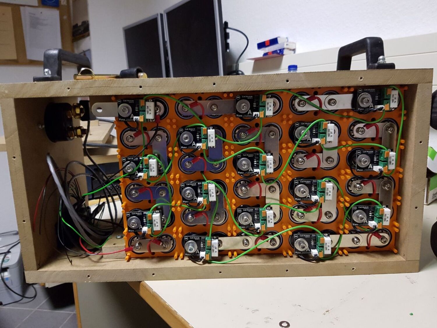
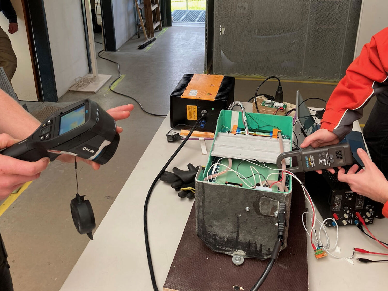
Battery
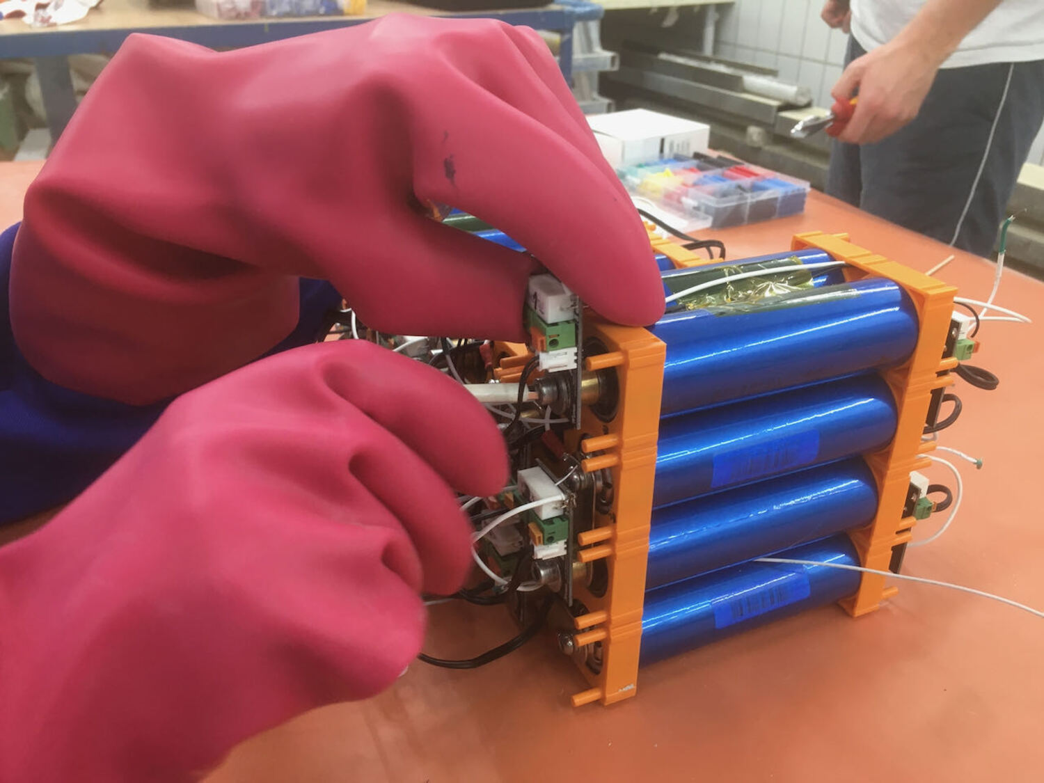
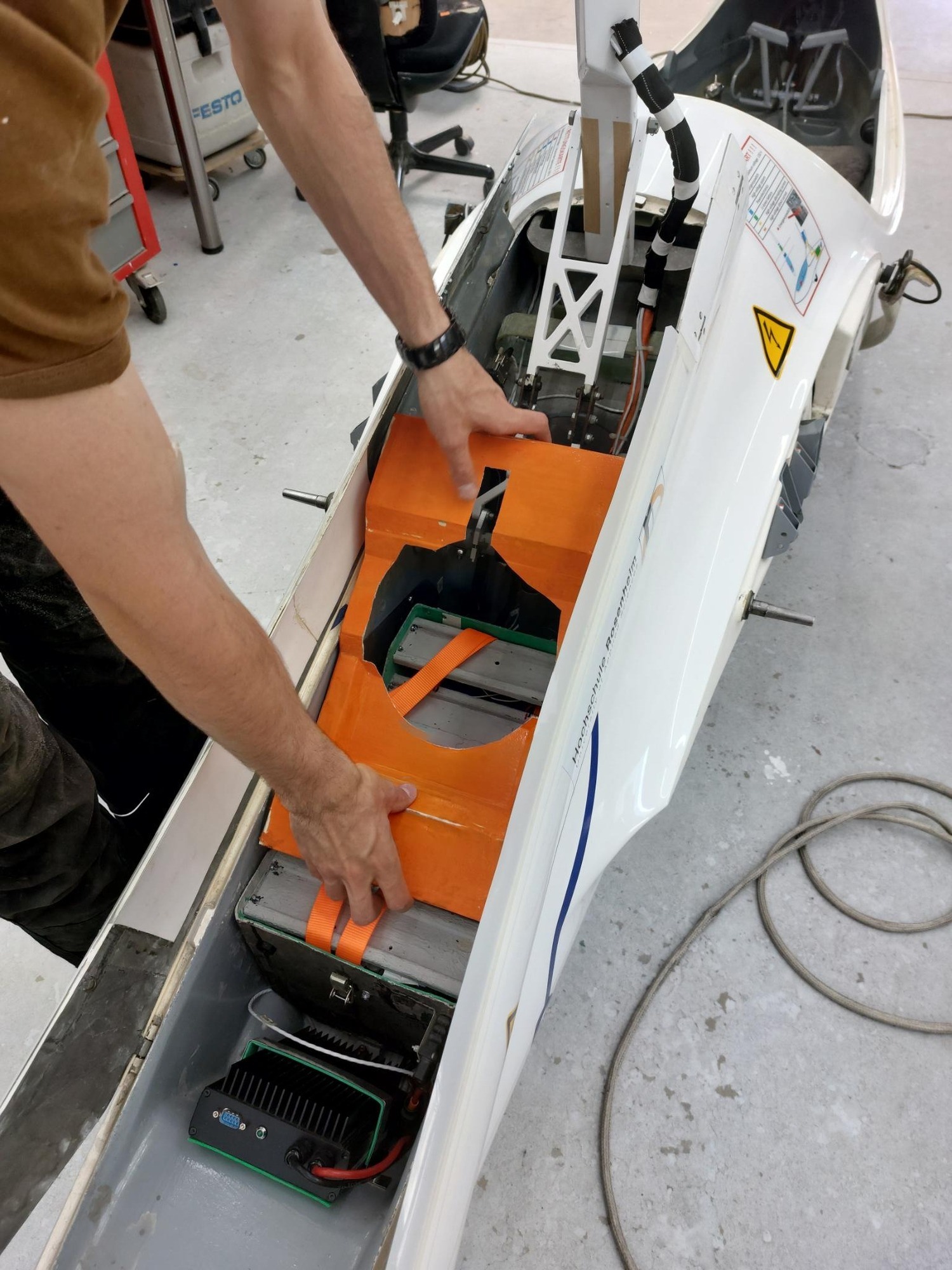
Due to difficulties in implementing the cell bonding concept, an alternative battery concept based on cells of type 38.140 S
of the manufacturer "Headway" is used, which is constructed from LiFePo4 cells. With a similar battery of the same modular LiFePo system, we did some ground testing of the FVA 29 successfully. For implementation in the motor box of the FVA 29, the number and arrangement of cells must be changed compared to the previous "laboratory battery".
the number and arrangement of cells must be changed. The drive battery is the energy storage device in the electric drive train. It is used exclusively to supply energy to the electric motor.
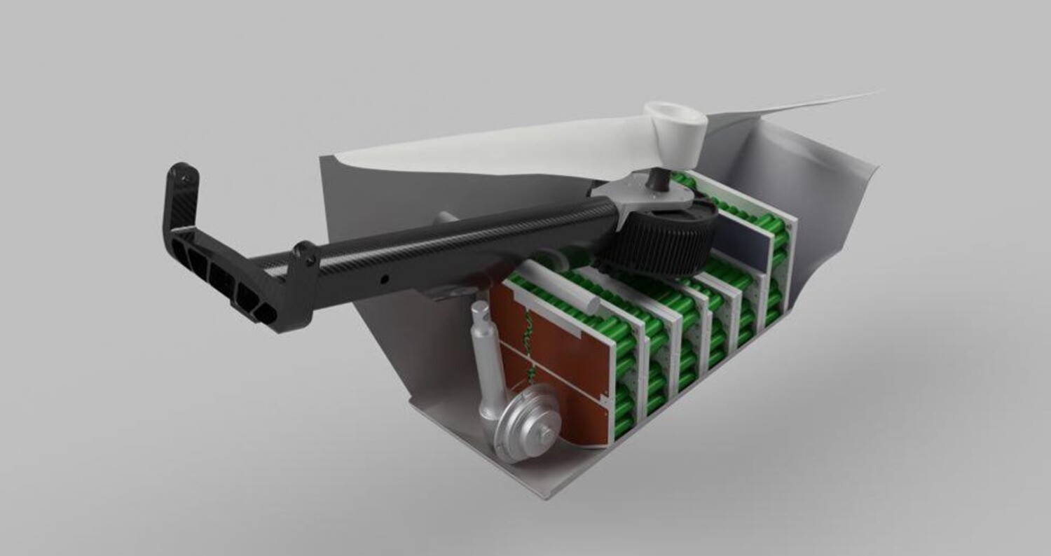
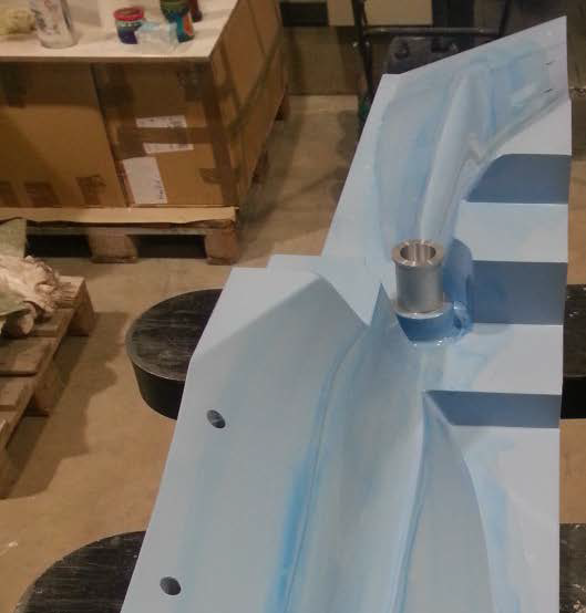
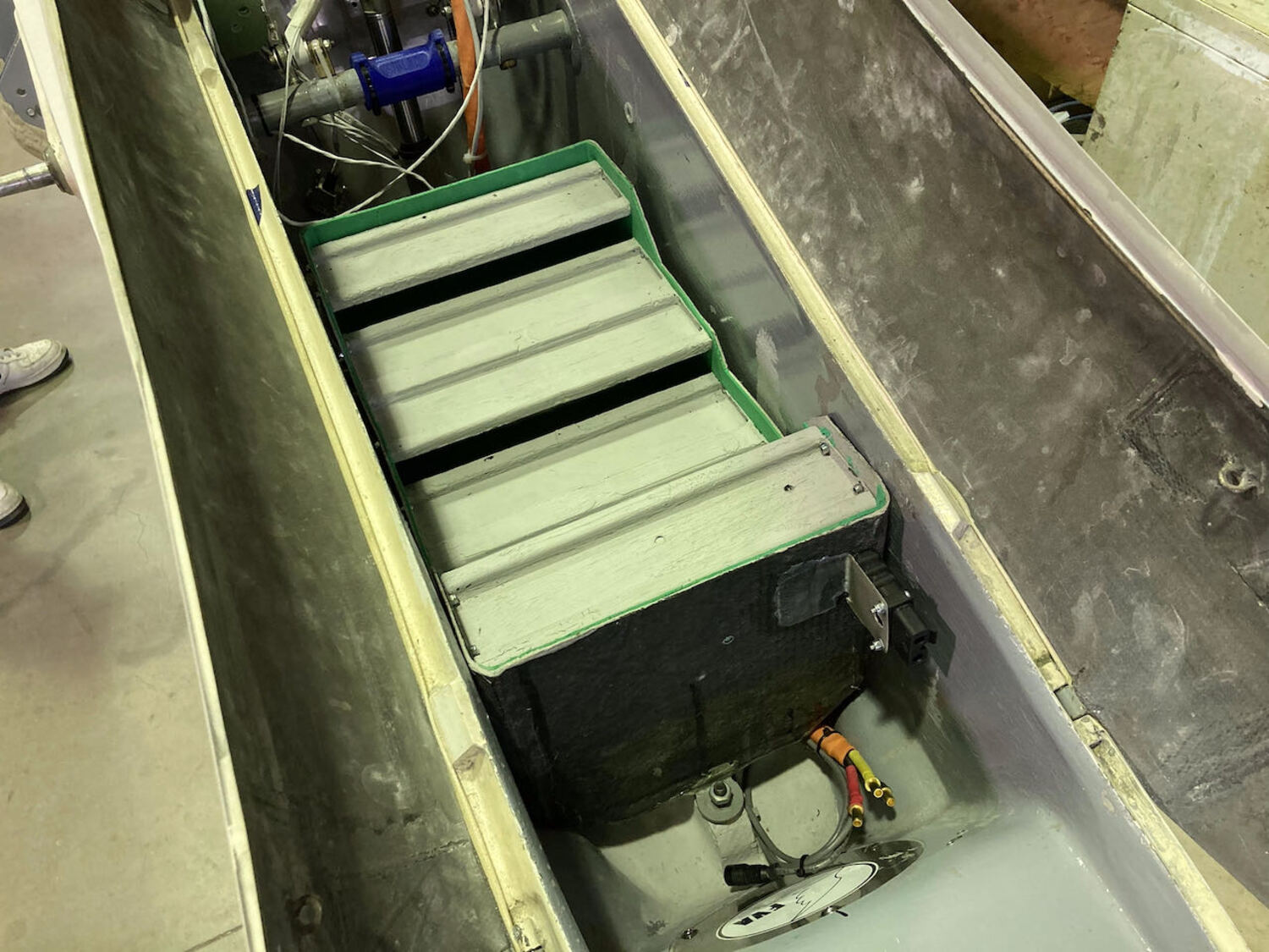
Battery box
The battery box is designed as a black box that must not allow any objects to escape in the event of a crash.
For this purpose, it must be able to absorb the total mass of the battery for all load cases and also reliably transfer these loads to the fuselage structure.
The box is made of CFRP with insulating GRP layers inside and outside. The box is mounted on three fittings that are bonded to the fuselage of the FVA 29.
Vibration and flutter behavior
Are there changes in the vibration behavior of the aircraft when the engine is extended?
This question was answered with a static vibration test. By simulating the corresponding assumed masses and excitation of the glider
excitation of the glider, the reactions are checked and natural frequencies determined.
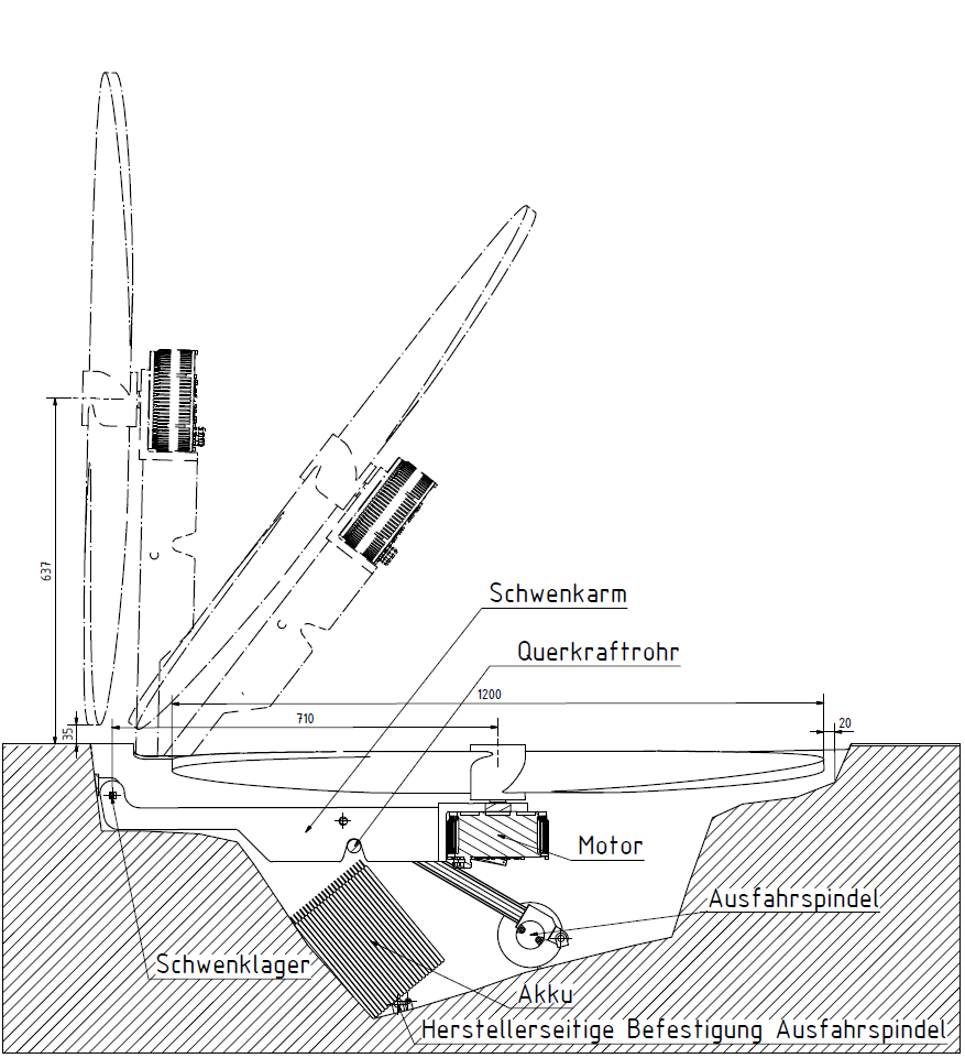
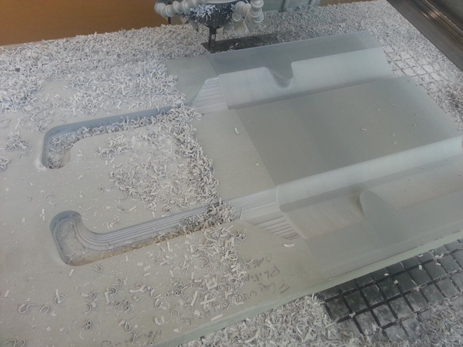
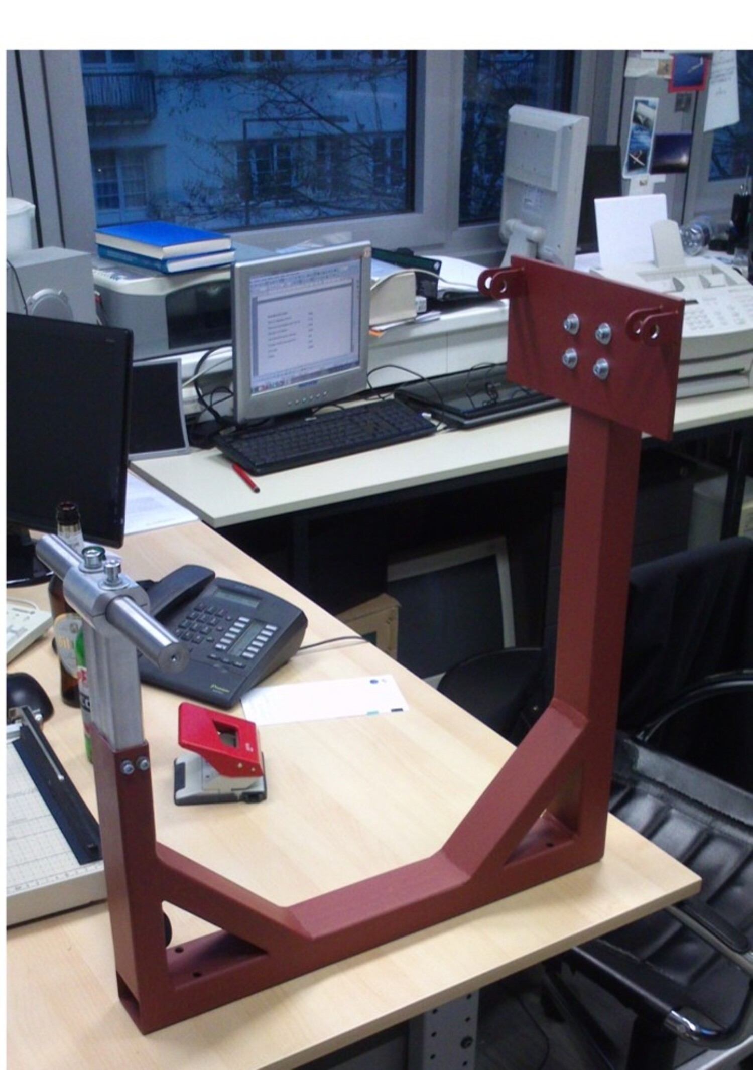
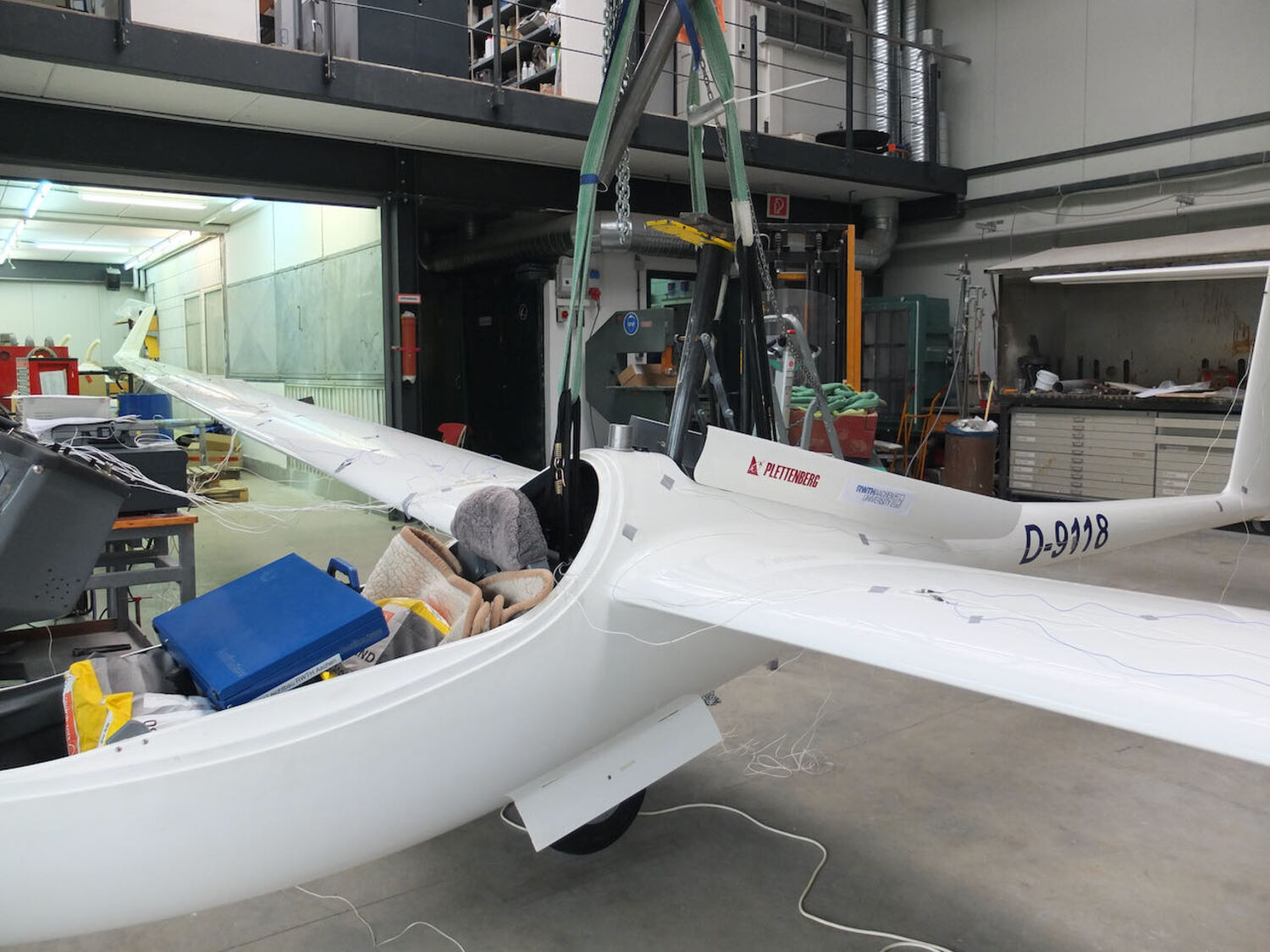
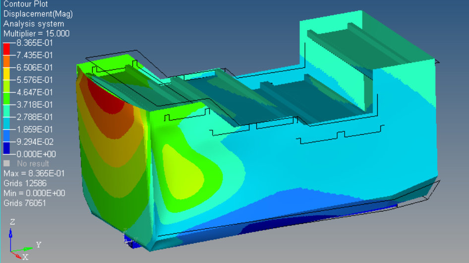
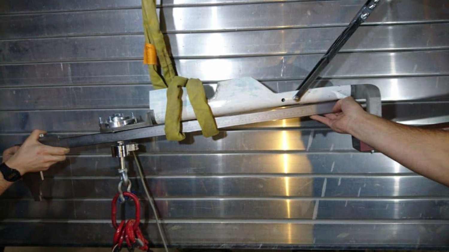
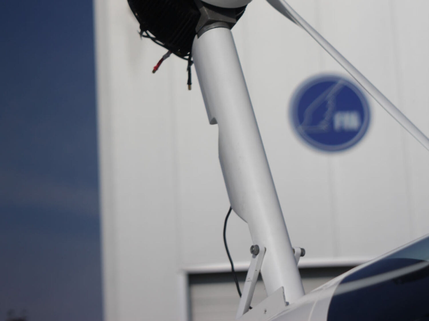
Mast
As a structural component, the mast must be able to withstand the applied loads without breaking.
No plastic deformations may remain during a load test. For this purpose, crash accelerations of
15g must be withstood. In addition, the innovative design of the single mast is particularly resistance-efficient.
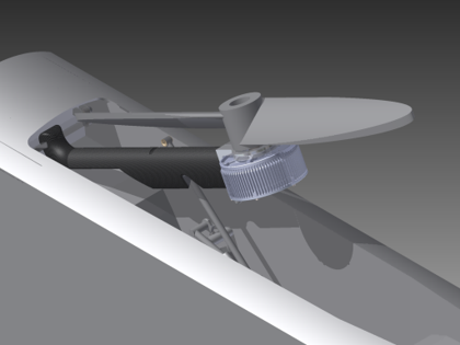
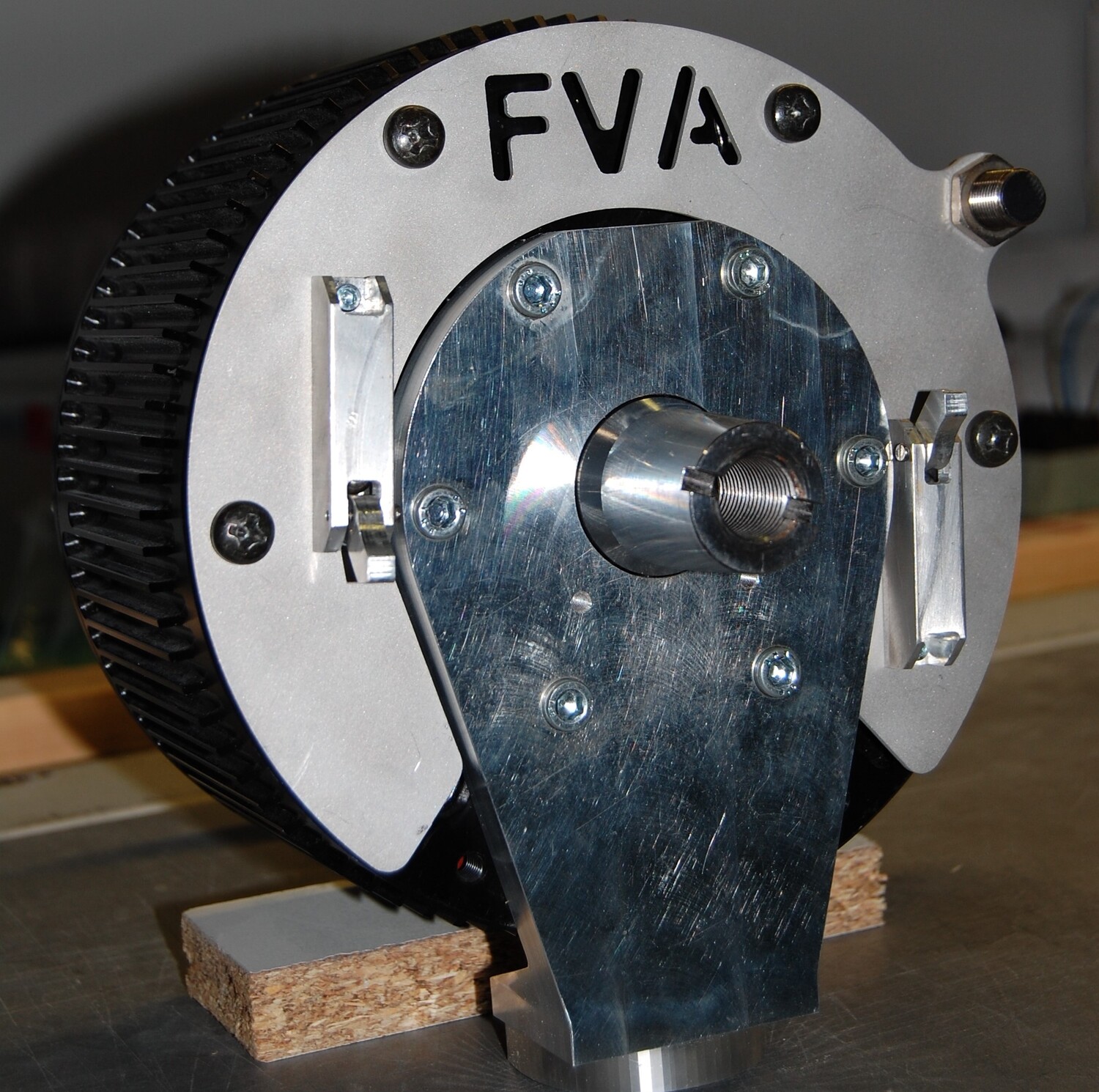
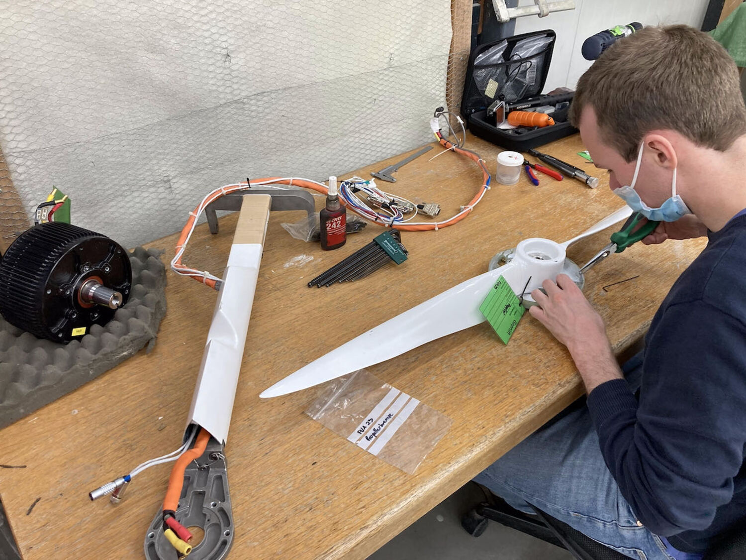
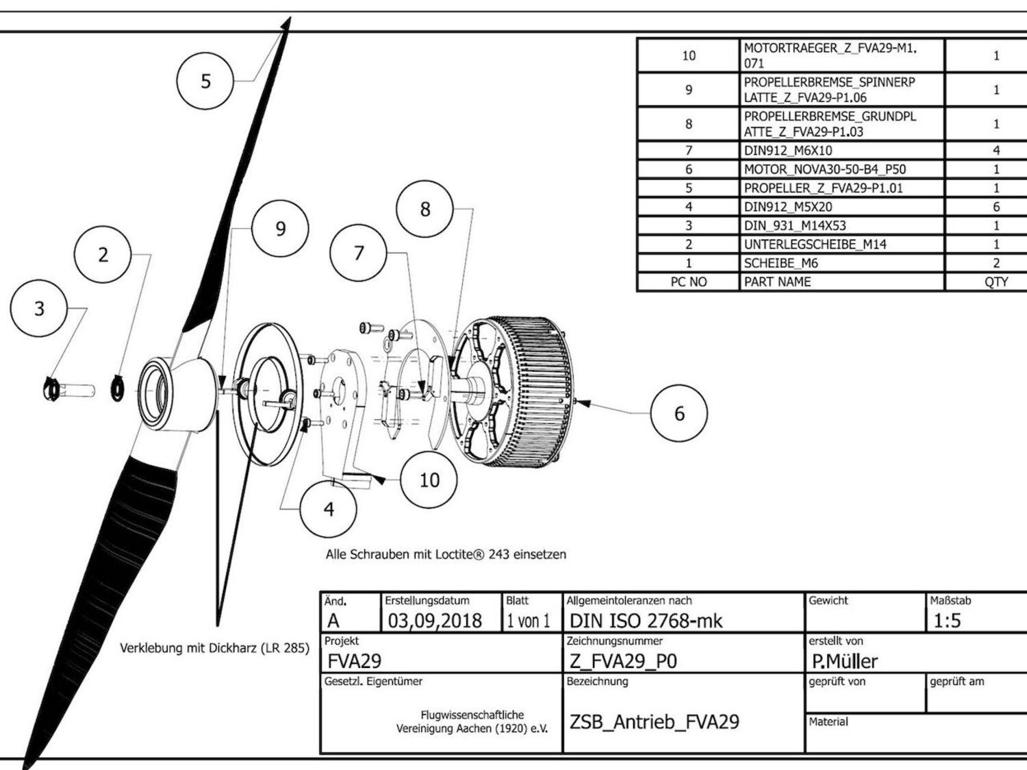
Propeller and propeller brake
The propeller must meet the structural requirements.
The aerodynamically optimized propeller drives at the operating point of 100 km/h with best climb performance.
If, due to a fault, the electrical braking force is not available due to the holding torque,
windmillling must be ruled out. For this purpose, the mechanical propeller brake provides a sufficiently large braking effect for flight operation.
System Safety Assessment (SSA)
In order to represent sufficient safety for flight operations,
a failed system must not pose a hazard. To this end, it is indicated, on the one hand, in accordance with the report on design and construction,
that already aviation-proven methods and experiences are practically implemented for the design.
The SSA primarily reviews the safety functions of the battery system and analyzes failure chains for severity of impact.
ECU cooperation
Cooperation on the development of a control unit for the electric drive train
with Prof. Mysliwetz, Rosenheim University of Applied Sciences
In a scientific work the control unit,
(Engine Control Unit (ECU) or EAGLE Control Unit), was developed.
Under the name EAGLE, the Rosenheim University of Applied Sciences, together with the RWTH, is preparing the further development and testing of the software for the cockpit instrument for integration into the aircraft and for flight certification.
The cockpit instrument is being prepared for integration into the aircraft and flight certification. The system state machine controls the start-up
and shutdown of the propulsion system. Compliance with MISRA-C:2012 development guidelines was also required for all developed source code.
Algorithms for estimating the charge and "state of health" of the propulsion system's lithium battery were also evaluated in the process
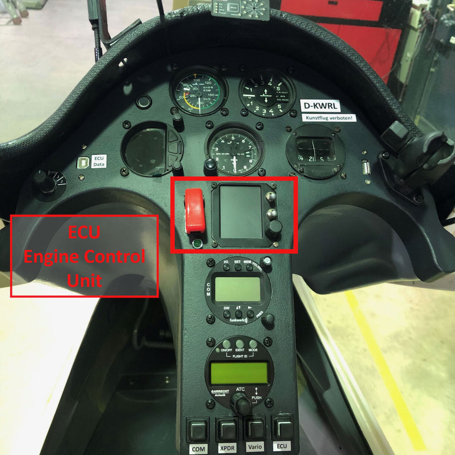
ECU Interface
The Engine Control Unit is the so-called EAGLE Control Unit of the EAGLE project of the
FH Rosenheim under the direction of Prof. Dr.-Ing. Birger Mysliwetz.
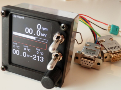
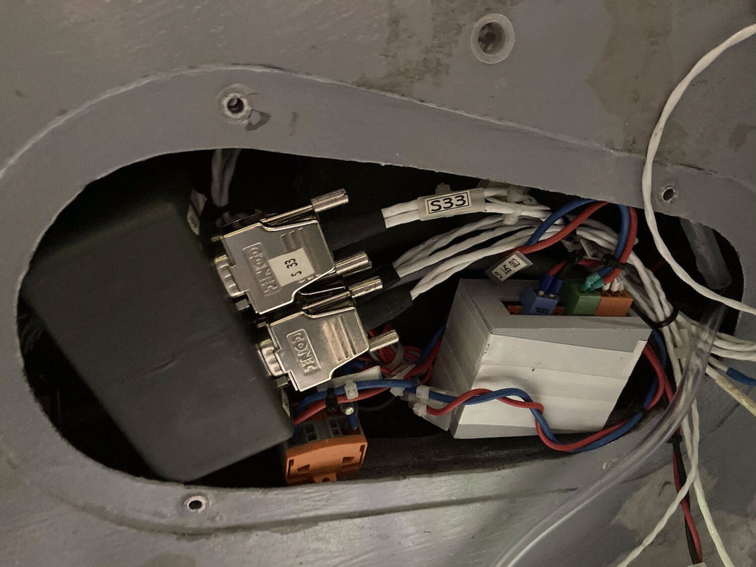
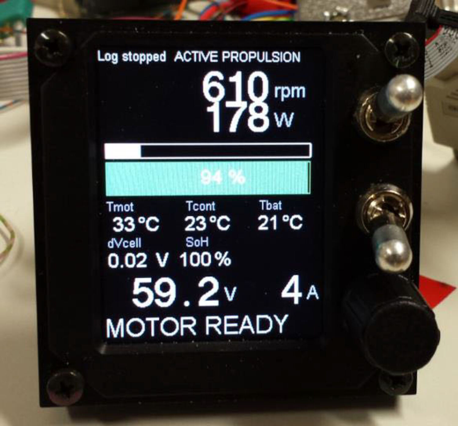
Description
This consists of a 36x48mm color LC display in the center, two blocking toggle switches in the upper right corner, and a rotary knob with a push button in the lower right corner.
The upper toggle switch is called the Up/Down switch, it specifies with its position in which state the system should currently transition. If it is up, the system will start to extend the motor, if it is down, the system will start to retract the motor.
The rotary knob is used to navigate in the software and to select the speed, the push button function is used to confirm inputs and messages.
The middle toggle switch is reserved for later use and is currently not wired.
The display shows the status data of motor and battery. This includes the speed (RPM), voltage as well as temperature values. This gives the pilot the correct overview of the system status.
Subproject: Structural Health Monitoring
Structure Health Monitoring (SHM) is a relatively new and important area of research in the context of fiber reinforced composites. The main reason for this is the increased difficulty in detecting damage to FRP structures.
While plastic deformation is a clear sign of damage in metallic materials, such visible deformation in fiber reinforced plastic (FRP) materials does not occur until final failure.
The original damage, which in metals would result in dents or the like, in FRP materials leaves only white fractures that cannot be seen through the paint,
but still represent a similar sign of a weakened structure. In previous calculations, therefore, a damaged structure is usually assumed in order to use large safety factors to determine the thickness of the required FRP layer.
This leads to unnecessarily heavy structures and reduces the efficiency of FRP materials enormously. This problem is to be solved by SHM. Different methods are used to detect possible damage,
in order to be able to assume that the structure is intact during constrcution.
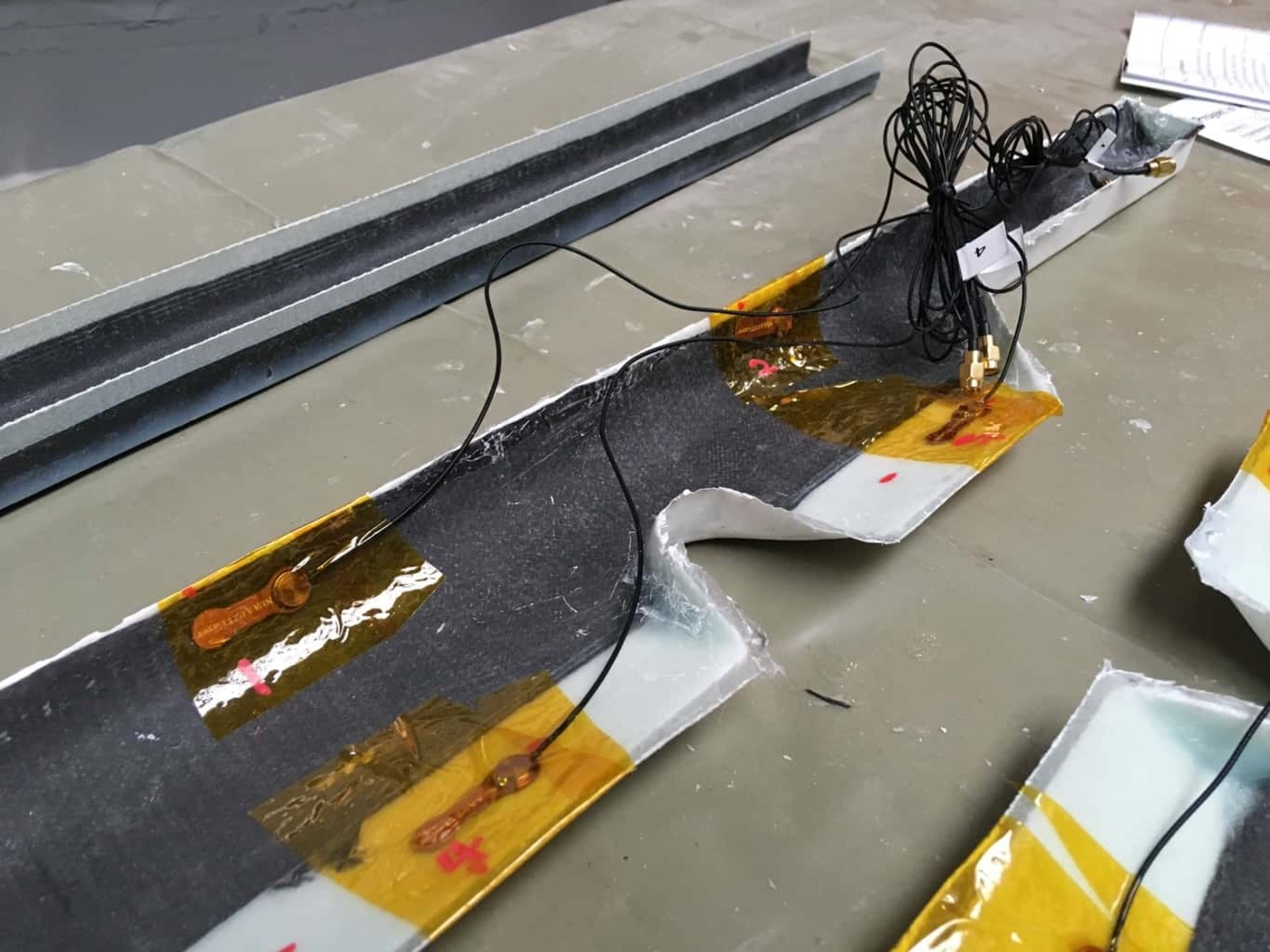
The Institute for Structural Mechanics and Lightweight Design (SLA) at RWTH Aachen University and the FVA cooperated from 2017 to 2020 on the practical application of SHM in aircraft.
The first research results of the institute were to be brought to the first flight application. The mast of the FVA 29 was chosen as the test component.
Piezoelectric actuators were bonded to the insides of the two half shells of the mast for this purpose. These actuators provide different voltages depending on their vibration and deformation. This electrical voltage is then measured and can be converted into actual deformation or mechanical stress to detect the load or possible damage to the shell.
Unfortunately, a first flight of the "SHM mast" could not be carried out during the project period, only ground tests were possible.
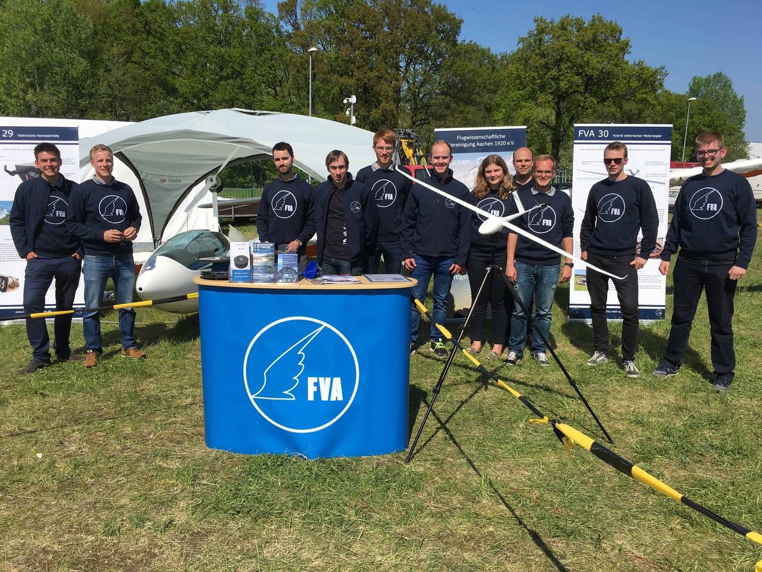
Questions? Join us!
Do you have questions about the project or would you like to join us? Then just write us anemail or meet us at the weekly meeting.
It doesn't matter which subject you are studying or which semester you are in. We are always looking for motivated team members who are committed to take part in our project independently. With us, you will get exclusive insights into aircraft development and can gain experience in aviation alongside your studies. We are looking forward to you!