Published: 29.01.2020 by FVA
To ensure the flight mechanical stability and controllability of the FVA-30, an adapted tail unit and appropriately dimensioned control surfaces are required. Last year, in coordination with the LBA (German FAA), conformity with parts of the CS-23 certification regulation was worked out due to the twin-engine nature of the FVA-30. The new requirements, together with more precise flight-mechanical coefficients and modified center-of-gravity estimates, prompted a new design calculation for the V-tail.
In the following flight mechanics design, the V-tail is dimensioned on the basis of critical design cases of longitudinal and lateral controllability and validated for all critical flight cases resulting from the certification regulations CS-22 and CS-23 via a flight dynamics calculation program. The figure below gives an overview of the principle structure of our flight mechanics computer.
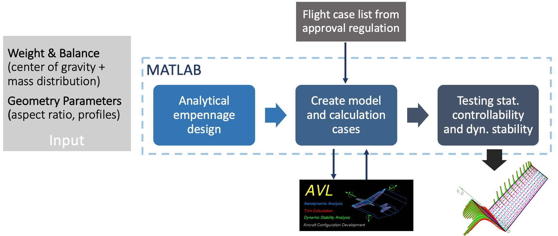
Structure of the flight mechanics computer with analytical design and numerical evaluations of the flight case list.
Analytical design: Basically, the empennage was first designed by an analytical, flight-mechanical analysis based on dimensioning flight conditions (i.e., by considering the moment balance under consideration of all relevant influencing factors). For the rudders, a maximum deflection necessary for lateral and altitude control (e.g. symmetric +/- 10°, antimetric +/- 15°, superimposable) and thus also a composite maximum deflection of 25° were determined in each case.
Numerical recalculation: Subsequently, the overall configuration was recalculated numerically (in AVL) for many different, expected flight conditions (including those from the certification regulation CS-22). In this case, the previously specified maximum rudder deflections, including a safety buffer for nonlinearities, must not be exceeded. The pitch and yaw moments generated by the engine thrust are included via trim conditions. Secondary effects, however, such as an increase in dynamic pressure due to additional blowing (propeller) or propeller jet constriction were not taken into account here.
The following critical flight condition & stability requirements were set as dimensioning for the tail unit for longitudinal movement:
- Take-off through (max. thrust) at VS0 (landing), i.e. the tailplane must generate maximum downforce
- Stability requirement negative moment rise (Cmα < 0)
- Stability requirement positive zero moment (Cmα > 0)
For lateral movement, the following critical flight condition turned out to be dimensional:
According to CS-23.147: Max. Pitching flight with additional unilateral engine failure at 1.4*VS1 (VS1: cruise minimum speed), while the remaining drive provides full thrust (at pos. pitching angles the failure of the left drive (looking in flight direction) would be critical for the required rudder deflection, for example).
The resulting maximum requirements for the tailplane area of a horizontal and vertical stabilizer equivalent to the V-tail are then converted into a corresponding V-tail according to the simplified V-tail theory.
Analytical Design
Approximation for the neutral point: The neutral point varies with the deflection of the flaps and the lift distribution. This means that ultimately only the numerical calculation will provide information about the stability reserve of the longitudinal movement. However, a conservative approximation can be used for the analytical design of the tailplane. The neutral point can be calculated by considering the Mean Aerodynamic Chord (MAC). For the FVA-30, the MAC and the neutral point position were calculated using the getMAC program of the Public Domain Aeronautical Software (PDAS).
Maximum rudder deflections to be assumed: With the profile used and a rudder depth of 35%, the rudder effectiveness decreases sharply for large rudder angles beyond 25°, so that effectively no additional lift is generated, but mainly drag. The tailplane profile selected by us (FX 71-L-150/30) shows here from approx. 25° flap angle at 35% rudder depth first larger deviations from the rudder effectiveness theoretically assumed for the tailplane design. In a V-tail, both the yaw motion is controlled by antimetric and the pitch motion by symmetric control deflections of the two rudders. Due to the previously mentioned saturation, the two control inputs combined should not exceed that rudder angle above which the rudder effectiveness assumed to be constant is no longer tenable. If these angles are nevertheless exceeded, a correspondingly increased rudder deflection must be expected to compensate for the nonlinearity. It must be differentiated whether the local lift coefficient, from which the nonlinearity occurs, is exceeded or whether the change of the zero lift angle and less the local lift at the control surface is in the foreground due to the inflow conditions (e.g. sliding flight in the lateral movement).
The tail unit geometry resulting from the analytical consideration and its flight mechanical parameters were finally compared with those of the e-Genius as part of a plausibility check. Overall, the newly designed empennage is very similar to the e-Genius from a flight mechanics point of view.
Numerical evaluation of all critical flight conditions
AVL provides the functionality of “Run Cases” for easy checking of different flight cases or flight conditions. This is a text file in which all state variables and trim conditions are defined for each flight condition (see figure below).
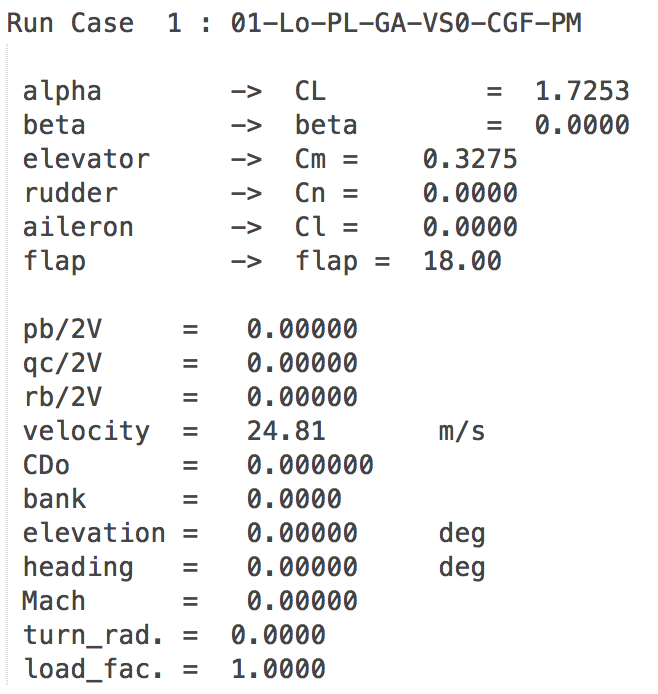
Example of the flight condition “Take-off on landing approach, foremost center of gravity with max. thrust”.
To enter the masses, AVL also offers the possibility to enter the masses and inertias as a text file. An example is omitted at this point. The sum of the individual centers of gravity then results in a total mass, the center of gravity and the inertia tensor. With this, calculations for dynamic stability are now also possible. If a calculation is performed in AVL, the results can be output graphically within the program in the Trefftz plane (suitable for visualizing lift distributions, cf. first figure below) or as a text file. In addition, qualitatively the lift distribution can be displayed three-dimensionally on the aircraft (cf. second figure below).
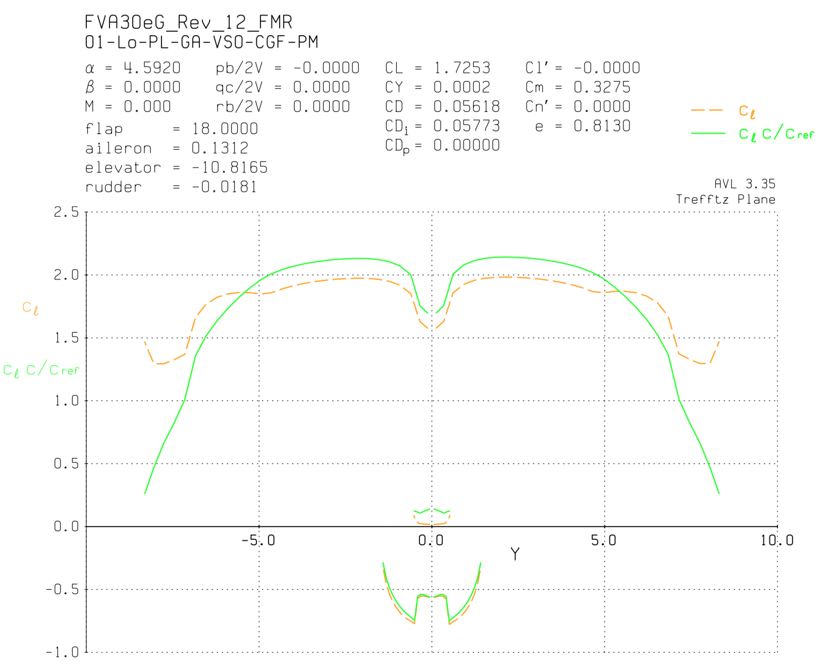
Lift distribution in the Trefftz plane for the flight condition “Take-off on landing approach, foremost center of gravity with max. thrust”.
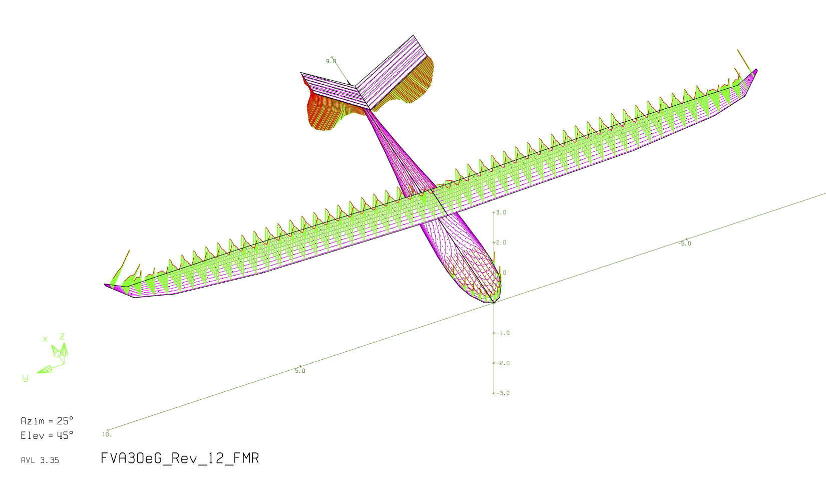
AVL geometry view with lift distributions for the flight condition “take-off on landing approach, foremost center of gravity with max. thrust”, fuselage approximated as a flat plate (cruciform fuselage)
Calculation results for critical flight conditions in longitudinal and lateral motion
The following table lists the necessary rudder deflections to achieve the respective critical flight conditions in longitudinal and lateral movement.

Overview of the results of the AVL recalculation: Required rudder deflections and the neutral point for the design cases in longitudinal and lateral motion
It is remarkable that the numerically determined rudder deflections in the longitudinal movement, which poses the more safety-critical requirements, are so close to the analytically calculated rudder deflections. Compared to the design case 01-Lo-PL-GA-VS0-CGFPM, there is only a deviation of 1.1% to the safe side. In the lateral movement, a larger deviation of 9.4% exists due to the worse condition of the problem. Apart from this, the static stability reserve is above 5% except for the fast flight case 04.2-Lo-CS22.161-TR-2.0VS1-CGH-PW. Since the fuselage influence on the aircraft neutral point is overestimated with the cross fuselage method, an even larger stability reserve can be expected. For the fast flight case, a center of gravity limitation of the most aft attitude may need to be applied during flight testing.
Since the rudder effectiveness decreases from a lift of cA ≈ 0.65 or the lift increase due to the rudder deflection shows a jump which is not mapped in AVL, a distinction must be made in the individual case between the geometric rudder deflection and the effective rudder deflection calculated in AVL. The decisive factor is whether it is a zero lift angle flight case cA;tail < 0.65 or a maximum lift flight case cA;tail > 0.65. Using the example of the Trefftz plane shown above, it can be seen that the maximum local lift coefficient is cA;tail ≈ 0.75. The geometrically necessary rudder deflection is thus ηV;max;geo = 12°. Consideration of all other flight cases of longitudinal motion (cf. plot in Trefftz plane) shows that all other lift requirements are below the design case 01-Lo-PL-GA-VS0-CGF-PM. Thus, the maximum symmetric rudder deflection is set to ηV;max;geo = 12°.
For the lateral motion, the lift requirements are well below the nonlinearity in the lift rise (cA;tail < 0.65), so that the maximum rudder angles for the antimetric rudder deflection at the V-tail do not need to be corrected. Due to the deviation of the numerical recalculation in the design case 54-La CS23.147ed-SFSEI-1.4VS1-CGB-SMSEI, the rudder deflection is raised to ζV;max;geo = 15°.
Thus, the empennage is fully designed in terms of flight mechanics and validated for static controllability. The final geometry with control surface deflections is summarized in the following overview.
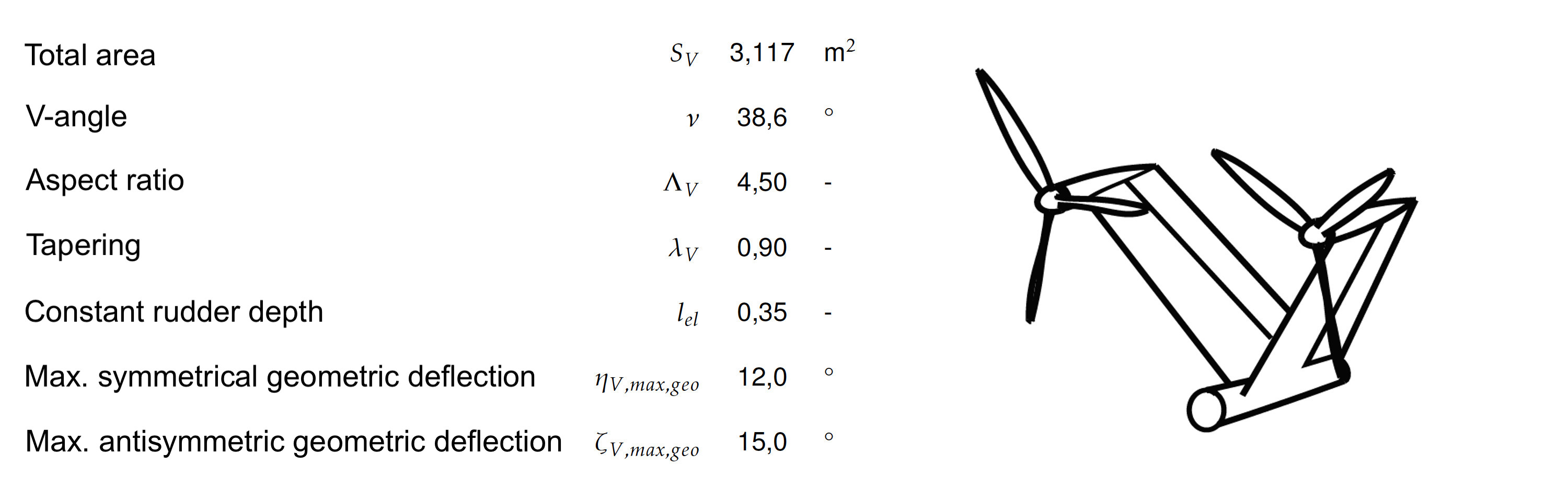
Summary of the final tail geometry of the FVA-30
Outlook
In the area of flight mechanics, the calculation of the maximum rudder torques now follows, which results in the requirements for the control system. In addition, the exact design of the V-tail geometry is to be determined in collaboration with the structure team.