Published: 16.08.2022 by Florian Mock
What is the most clever way to combine the progress of one’s own studies with the FVA while still advancing a project as sustainably as possible? By writing a scientific paper required in the course of studies within an FVA project! This is what Valentin Storre and Florian “Flock” Mock recently did.
A concept for the engine mount of the FVA 30 had existed for some time, which was developed as part of a master’s thesis on the structural design of the tail unit. However, since the engine mount or the engine nacelle as a whole was not the main topic of this thesis and no detailed design process took place for this assembly, the concept still had some weaknesses. Therefore, a new concept for the engine nacelle space was developed using a standardized design process. This provides for an engine mount that carries the mechanical loads of all components of the assembly and introduces them into the tail structure. In addition to the engine itself, the main components to be considered are those for cooling the engine and power and data electronics. For aerodynamic reasons, the engine nacelle will of course be clad, but the shell will not carry any loads except for its own weight.
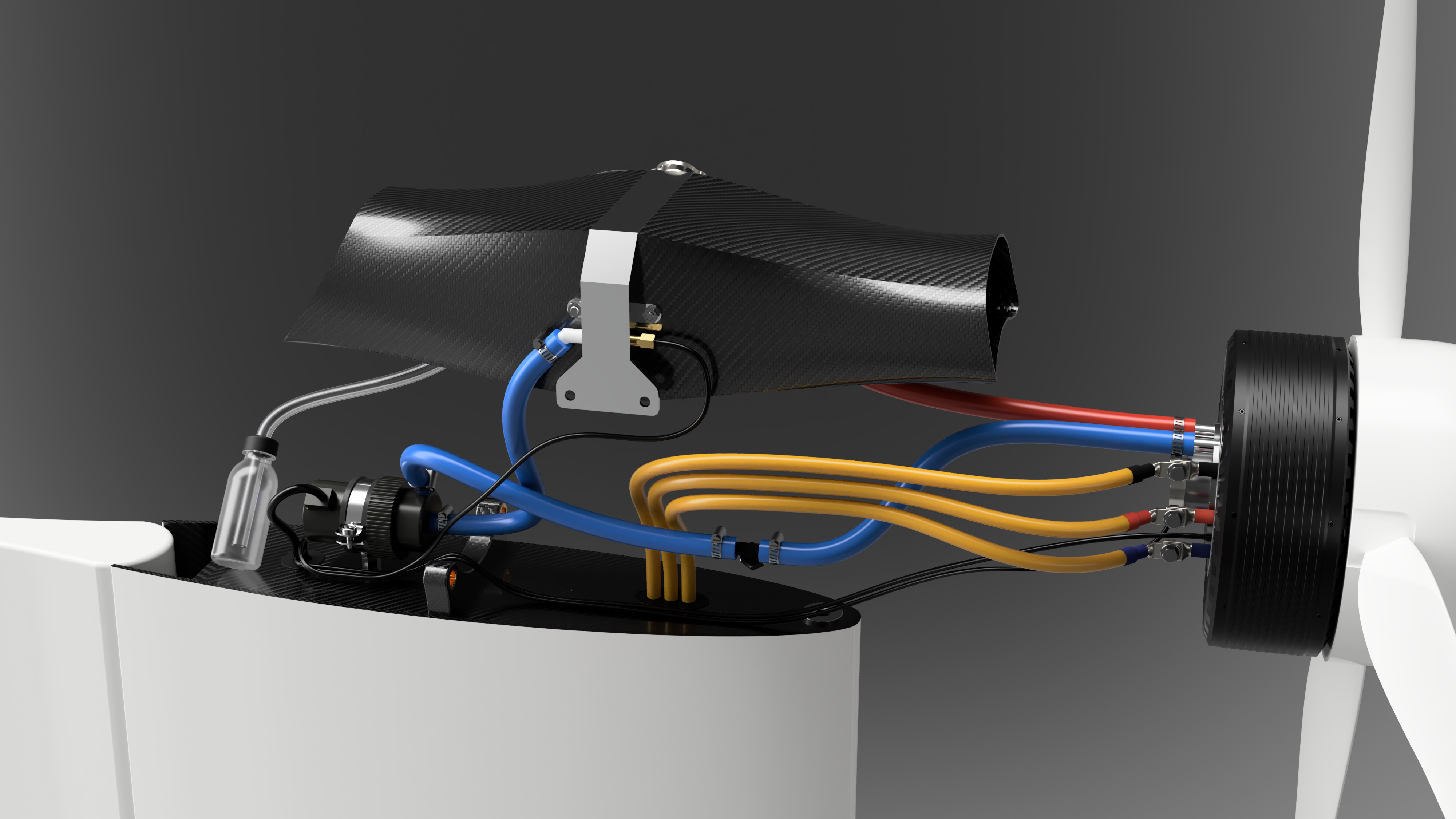 Arrangement of the elements of the cooling circuit and electronics
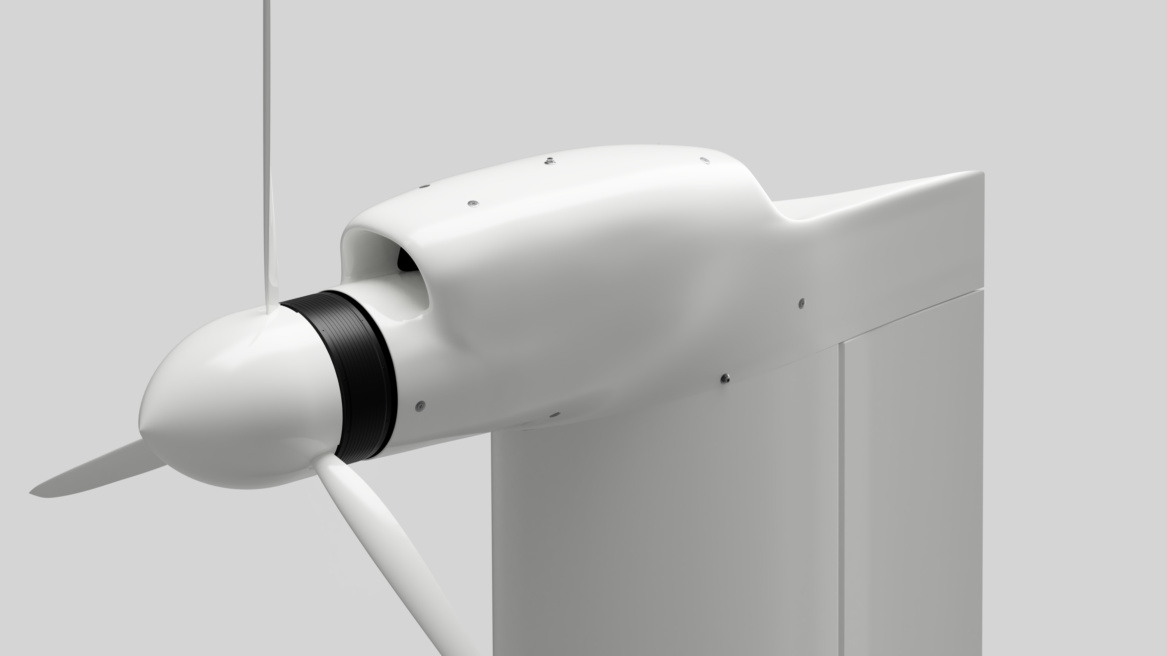 Aerodynamically clad engine nacelle of the FVA 30 with air inlet for flow through the radiator
After the concept for the assembly was finished, “only” a suitable engine mount was missing, which would withstand the loads caused by the masses of the components accelerated in flight. Due to the large distance between the engine nacelle and the center of gravity, the aim is to keep the mass as low as possible, since even small masses lead to high moments due to the large lever arm. For some time, therefore, the idea of a topology-optimized and 3D-printed engine mount has been haunting the structural team at FVA 30. This quickly gave rise to the topic for a project thesis comparing such a concept with a truss made of tubes welded together, which is typical for such applications.
First, the limitations of the available installation space were defined by the other components and the mounting of the engine mount on the fin of the empennage. A three-point mounting appeared to make the most sense, with one bearing point located near the airfoil nose on the rib and the other two integrated directly into the tail spar. This has the advantage that the loads are transferred directly to the supporting structure. Furthermore, in order to design a component, it is essential to calculate the expected loads. This was done by observing the required load cases from the approval regulation CS-22, which specifies accelerations that, when multiplied by the component masses, result in forces to be borne by the structure. After a detailed comparison of the mechanical properties of various materials, the decision was made to use aluminum, as this allows the lowest masses to be achieved. However, this material also has its pitfalls, which have to be taken into account especially during welding. With this information, two engine mounts can now be designed. One is a truss made of welded tubes, the other is a topology-optimized free-form body, which is manufactured additively in the 3D printer.
Both concepts have various advantages and disadvantages. For example, it is easily possible for topology optimization software to calculate a structure around existing obstacles. Geometric constraints due to additional components can thus be taken into account without much effort. Furthermore, the manufacturing after the design is not a big hurdle anymore, since it is mostly done by a machine. On the other hand, in this application, only the printing of solid bars is possible for reasons of surface quality. This results in large masses in relation to the mechanical output.
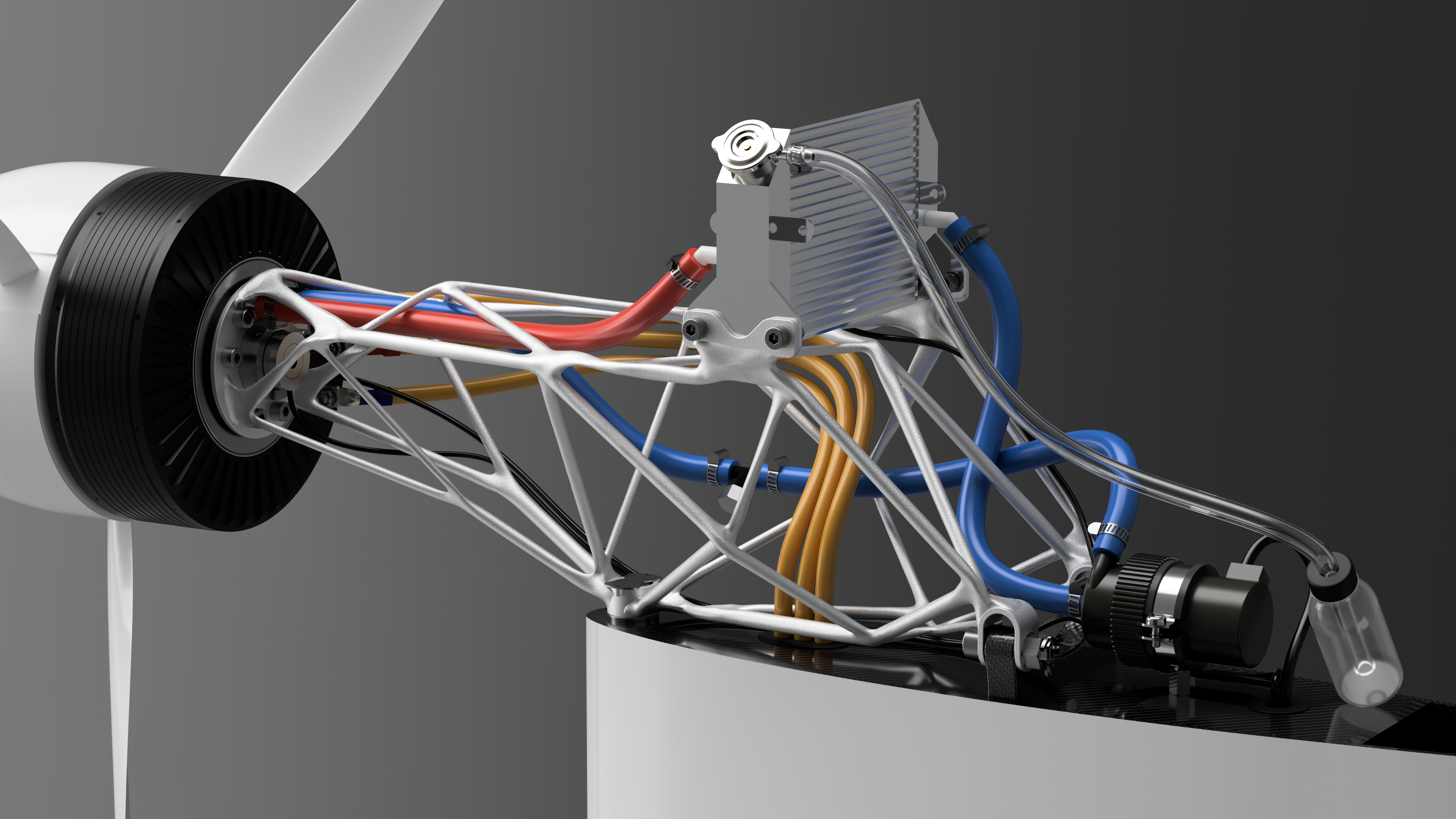 This is how a free-form body could look like as an engine mount in the assembly
In the case of a truss made of welded tubes, the geometry of the individual elements cannot be adapted to the obstacles, which complicates the fulfillment of the installation space restrictions. In addition, the complexity of the truss is limited because it must be welded by hand at the end. However, these disadvantages are ultimately significantly outweighed by the mechanical advantages of tubes over solid bars. In a mass comparison, the welded trusses perform significantly better than the additively manufactured solid engine mounts.
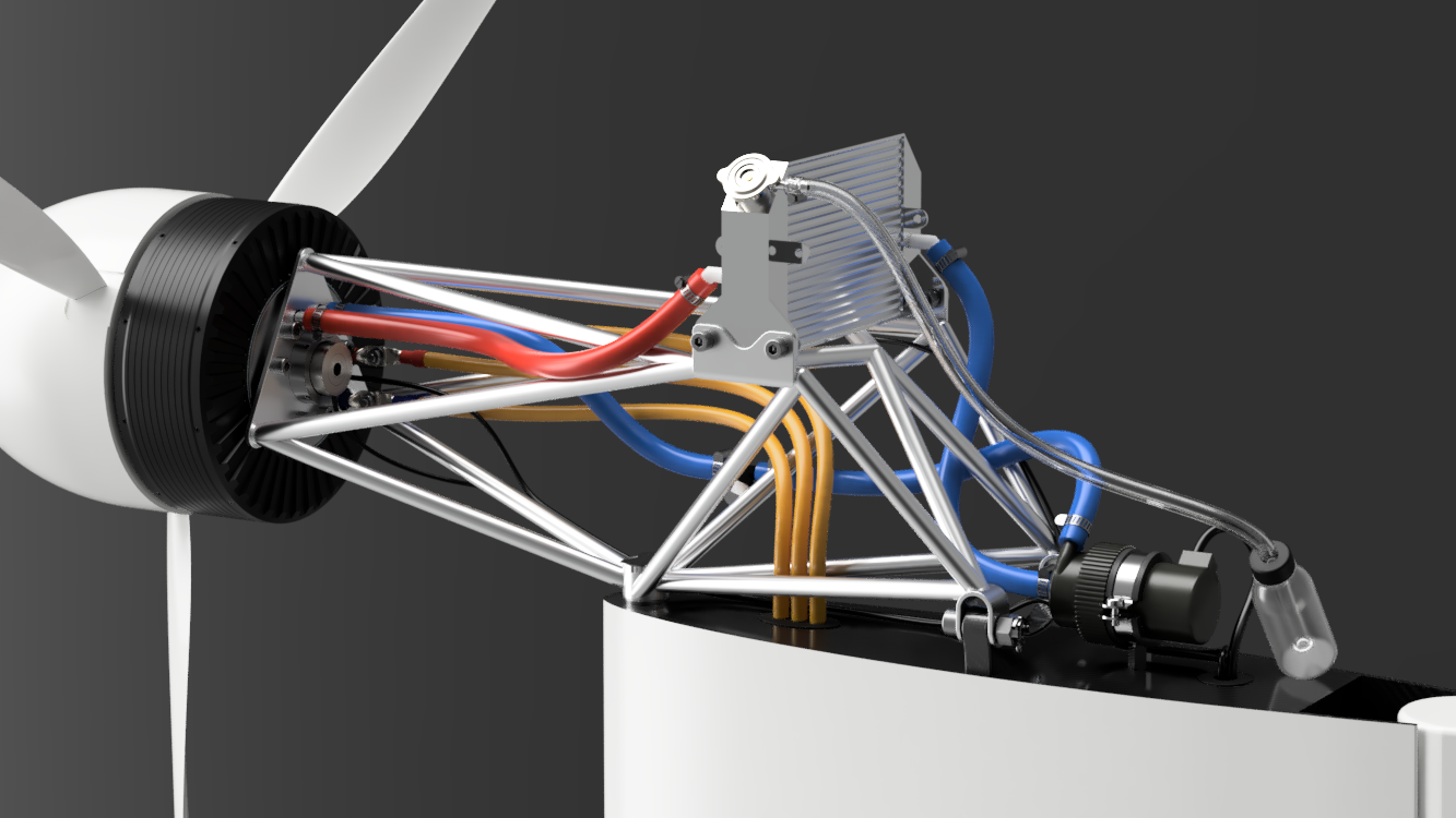 This is how a tubular framework could look like as an engine mount in the assembly
Therefore, the result of the project thesis is an engine mount, which consists of aluminum tubes and to which all required elements of the assembly can be attached. To simplify production, the design was adapted at the end so that all tubes have the same cross-section. This engine mount now meets all the required safety factors with a total weight of 705 grams.
The project work is based on a preliminary geometry of the tail unit. As soon as it is finalized and a procedure for approval is agreed with the German Federal Aviation Authority, production of the engine mount can begin.