Published: 4.01.2021 by FVA
Due to the landing gear arrangement of the FVA 30, a tail wheel is required. The specific requirements for this are precise controllability for rolling on the ground, sufficient damping and a design that keeps drag values as low as possible. However, retraction and stowage during flight are not mandatory.
The development of the tail landing gear initially began with creating an overall concept for the superstructure. The selection of the current concept was based on inspiration from other aircraft in this class, motorsports and our own considerations. Framing the development were limits, safeties and minimum requirements from other project teams. These include weight limits from Weight & Balance, vertical component dimensions to realize the required angle of attack on the ground, and basic minimums from EASA’s JAR-22 construction regulation. According to JAR-22, dynamic spur loads during a spur landing (JAR-22.481), for example, can be determined for various masses. These values represent the highest possible load experienced by the component under borderline conditions not classified as “abnormal”.
Also, the forces during rotary landings represent a minimum requirement. The current concept consists of a multi-part landing gear structure consisting of a lower fork with the wheel axle, an upper beam in which the control system is integrated, and a suspension in which the rotatable bearing of the control system, as well as the fastening elements for connection to the aircraft structure, are housed. Of course, a damping system is also found in the structure. This is located between the upper beam and the lower fork. At this time, a decision has yet to be made as to whether a hollow rubber spring or a hydraulic damper will be used. The control of the tail gear is to be realized by ropes which carry a pure rudder signal. These cables are attached to the control points with a thimble and a bolt (with split pin or wire securing). This allows easy disassembly for maintenance or repair. The development of tail landing gear has gone through ups and downs since its inception. Concepts were designed, then discarded because they were unsuitable for this load case of the FVA-30. But there were also components that fit into the overall FVA-30 system at the first attempt. All in all, the tail landing gear is not only an important element of the aircraft, but due to its position at the greatest distance from the center of gravity, it is an influential factor for many other trades on the aircraft and must therefore be matched as closely as possible to all of them.
![]()
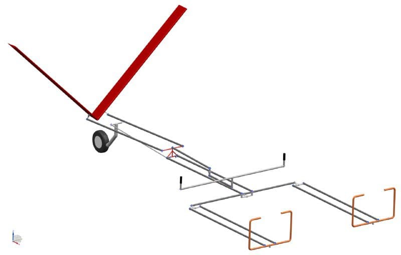
First design of the tail wheel
Tail wheel and rudder control
The design of the flight control system began in April 2020 based on a bachelor’s thesis that proposed a control scheme for the V-tail setting of the FVA-30. A mechanical mixer is positioned between the cockpit and the tail to translate pilot input into proper control surface movement. By the end of September, the design team had translated the scheme into a rough CAD model that allows for the side-by-side seat layout.
A sketch of the entire rudder control system was created for the design. The sketch provides a structure for all components of the control system, which are first designed and then constructed, starting with the mixer. This is to be positioned below the range extender. The mixer was designed as part of a scientific thesis. This design was used for the construction of the mixer and will soon be inserted into the model together with the linkage.
Sketch of control and mixer