Published: 5.12.2020 by FVA
After the complete sizing and design of the V-tail of the FVA-30, an important effect affecting the tail was studied again in more detail during the last semester: The interaction of the propeller wake with the flowed-around control surfaces on the empennage and the resulting rudder effectiveness significantly influences the verification of longitudinal and lateral stability both in twin-engine operation and in single-engine operation (one-engine inoperative, one-sided propulsion failure) and thus also affects the design of the empennage. Here, the propeller wake and the tail surfaces interact by rotating the aerodynamic inflow vector and changing the dynamic pressure. In consultation with the LBA (German FAA), we concluded that this effect needed to be studied in detail to ensure safe operation under all circumstances. Since the effect of propeller-tail interaction is sometimes very pronounced in the propellers dimensioned for the FVA-30 and their performance in the various flight cases, a method for recalculating this effect was determined. This was used to redetermine and evaluate the required rudder angles. It was possible to integrate the effects of the twist superposition of propeller and tail into the existing model and the recalculation without much additional effort.
In the following, these aspects are explained in more detail, the related developments to date are recapitulated, and reference is made to the effects occurring that are relevant for flight mechanical stability.
Since the actuators are mounted at the ends of the V-tail, the thrust of the propellers on the tail causes an undesirable pitching moment, depending on the setting angle of the actuators. This moment cannot be neglected for flight phases with high thrust requirements, such as takeoff or takeoff-through. To compensate for this, it would be possible to tilt the drives, but this would result in an asymmetrical flow to the propellers. However, this would result in an increased alternating load on the propellers as well as losses in propulsion efficiency. For the FVA 30, the above problem is addressed in three places. First, the drives are tilted slightly and aligned along the flow in cruise flight to keep blade loading low. Second, the direction of rotation of each propeller is selected so that the inboard propeller blade moves downward (inboard down, see figure below).
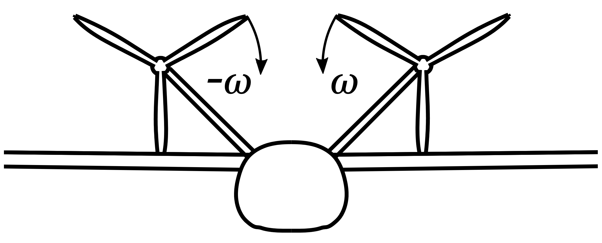
Direction of rotation of the propellers, both Inboard-Down
The twist induced by the propeller thus reduces the local angle of attack on the tailplane, which then generates increased downforce and partially compensates for the pitching moment. In addition, the local reduction of the angle of attack prevents a stall at the tail unit. It should also be mentioned that the propellers do not generate any resultant moment about the longitudinal axis of the aircraft and no resultant gyroscopic moments due to the counter-rotation.
Thirdly, the remaining moment is controlled by the rudders, whereby it is important to keep this proportion as low as possible in order to relieve the pilot and enable efficient flight with low rudder deflections.
Now the differences in the various flight cases will be discussed in more detail. In twin-engine operation, the elevator effectiveness is reduced in the pitching-down direction, since both propellers rotate inboard-down as described above. Similarly, in the rudder case, one rudder of each respective wing per tail is reduced in effectiveness in both turn directions. This applies especially to the critical flight case of takeoff through and the trim cases from CS-22 with the speeds 1.2 – 2.0 VS1 (VS1: minimum cruise speed). In the case of an engine failure on one side (one-engine inoperative), rudder deflection on the tail must fully maintain rudder function and compensate for any instabilities. This requires increased rudder deflection because the effectiveness of the deflection of the rudder on the tail surface on the side where the engine is still running is reduced in one direction. This effect applies to the rudder and simultaneously to the elevator due to the V-tail configuration. The failure of one propulsion unit also creates a drag force due to windmilling. No data on windmilling effects have been collected to date, and windmilling effects have yet to be investigated. The effect of propeller-tail interaction will occur especially in push flight, for example in the critical flight case CS23.147 – “Push flight with +/- 15° push angle and unilateral engine failure”. This occurs precisely when the aircraft flies at the maximum possible angle of bank based on the design of the rudder. The additional moment from full thrust of one engine and windmilling of the other engine now has the orientation that the FVA-30 turns further out of the approach flow. As a result, the angle of attack at the tail unit exceeds the maximum angle.
Verification in AVL
The vortex lattice method, also known as Vortex Lattice Method (VLM), is used for the verification calculation. Since in AVL (VLM code) only the skeleton line of the profile is considered, a change of the local angle of attack is equivalent to a corresponding opposite rotation of the skeleton line. More detailed information on the VLM used can be found in the Progress Report of SS20. Since the effect of the propeller-tail interaction is sometimes very pronounced for the propellers dimensioned for the FVA-30 and their performances in the different flight cases, the recalculation of this effect is presented in the following.
The propeller generates a strongly unsteady flow field behind the rotor plane and from this a twist which is imposed on the tail surface behind the rotor. This twist induces an angle of attack which can be determined in the area of the propeller. The resulting distribution over the propeller plane is shown in the following figure as an example for the case during takeoff.
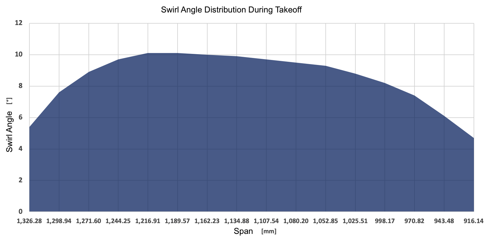
Swirl angle distribution during takeoff
This shows the extent to which the propeller imposes a downwash on the tailplane and the magnitude of the induced swirl angle. Considering the swirl angle over the span of the V-tail flowed around by the propeller jet, the effect of the propeller-tail interaction can be modeled. This can be modeled in AVL via a segment-wise discretization of the swirl angle distribution and the change of the local setting angle over a full-scale camber flap. A total of 15 segments have been discretized and in them the swirl angles have been entered into the geometry file starting from the propeller calculation. The geometry of the empennage itself was not influenced, since the corresponding positions of the segments were previously determined to the empennage positions. The segments extend over the entire chord depth of the empennage, the rudders are not influenced by this in their geometry. By means of a weighting of the individual deflections at the different sections of the tailplane, the occurring angle of attack distributions can now be modeled.
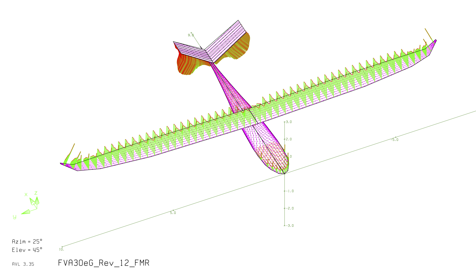
AVL geometry view with lift distributions for the flight condition “take-off on landing approach, foremost center of gravity with max. thrust”, fuselage approximated as a flat plate (cruciform fuselage)
In the figure above, the lift distribution is shown using the example of takeoff. The changed angle of attack distribution is directly reflected in the lift distribution at the empennage. In the next section, the critical flight cases (including takeoff, one-engine inoperative and trim cases) are calculated in order to first determine an estimate of the resulting control surface angles and, if necessary, to derive a trend of the maximum control surface deflections.
Recalculation of critical flight cases
For the recalculation of the resulting rudder deflections in the individual flight cases, the flight case-dependent swirl angle distributions were integrated into the AVL method. From the observation of the flight performance and the testing of the drive train, a new, optimal operating point was found, so that the new cruising speed is now 155 km/h. In flight mechanics, this results in a new setting angle of wing and tail to ensure stability and controllability in all relevant certification cases. This has now been shifted to the optimum, insofar as the flight mechanical design permits. Without considering the angle of twist, an angle of incidence of 3.5° on the wings and -1° on the V-tail can be achieved. If swirl effects are taken into account, only a setting angle change of 3° on the wings and simultaneous change of the setting angle on the V-tail of -0.5° can be made.
With the profile used and a rudder depth of 35%, rudder effectiveness decreases sharply for large rudder angles beyond 25°, so that effectively no additional lift is generated, but mainly drag. As a result, the composite rudder angle of attack should never exceed the 25° limit, which is not the case here. In addition, the individual rudder values for elevator and rudder are also not far above the maximum values of approximately 12° (elevator) and 15° (rudder) previously specified. With these values for the required rudder deflections, it can be demonstrated with the current status of Weight & Balance and the flight performance consideration that with the method used here to map the propeller-tail interaction, the stability and controllability of the FVA 30 is given.
By means of a swirl angle distribution, a better estimation of the occurring rudder angles can now be made, so that the real occurring rudder deflection angles are lower. However, the method with AVL has some limitations in the context of propeller modeling, especially a complete modeling of the propeller wake with respect to the dynamic pressure change is not possible. There, the flow field or the inflow vector cannot be modified locally. Thus, additional blowing cannot be modeled. By considering the increased dynamic pressure in the propeller wake, even lower estimates of the rudder deflection angle can be made.
Influence of the change in dynamic pressure: With a rough calculation it can be easily shown that the dynamic pressure behind the propeller plane is significantly higher than in the approach flow of the aircraft (quadratic relationship of the dynamic pressure behind the propeller plane with the flow velocity). In the case of takeoff, the increase in dynamic pressure amounts to almost 60 %. This allows the assumption to be made that the rudders also have an increased effectiveness due to an increased dynamic pressure, even if a spin-induced angle of attack initially reduces the effectiveness of the rudders.
Outlook
The method of calculation is limited in the implementation of a complete propeller-tailplane interaction, since the dynamic pressure plane behind the propeller plane cannot be represented. However, this gives an estimation to the safe side, since just this dynamic pressure change behind the propeller plane cannot be taken into account and an increased rudder effectiveness is expected. With the current status of the weight & balance and flight performance considerations, the FVA-30 is stable and controllable in the flight cases to be verified.
However, a review of all critical data and geometries used in the teams will continue in the coming weeks. This will ensure that no inconsistent data has been used at the start of manufacturing and that manufacturing can commence in early/mid 2021 together with the newly established manufacturing team. As soon as the conditions (Covid-19) are again given to investigate the windmilling behavior of the propellers, tests can be performed on the test rig at RWTH or FH Aachen. Thus, as soon as data from the test runs are available, they will also be included in the flight-mechanical analysis, so that a numerical recalculation with all potential risks (failure of a drive unit incl. windmilling during push flight) can be fully completed. In addition, the verification process is now being discussed with the LBA and, in parallel, initial material procurement for the fracture tail unit is being carried out. A supplementary examination of the flight behavior in conjunction with the flight performance computer will also be considered in the new year by means of combined flight simulation of (dynamic) load cases.