Published: 24.09.2020 by FVA
In the last article, a first load comparison between the wings of FVA-30 and e-Genius was carried out. Based on the section loads of the wing determined with our load calculator, it was now possible to determine a first strength verification for all wing structural components.
Design calculator of the e-Genius wings
The strength verification of the e-Genius wing geometry was performed at the Institute of Aircraft Design (IFB) of the University of Stuttgart using the design calculation software Mathcad and is divided into the three main sections: Wing Structure, Wing-Wing Separation and Wing-Fuselage Separation.
In each of these separately considered sections, structural models of the entire e-Genius wing are created on the basis of defined material and geometric properties, and all load-bearing structural components are dimensioned and tested for sufficient strength. The construction method selected was that of a single spar, a load-bearing sandwich shell and stiffening ribs, which is suitable for practical use and common in small aircraft construction (see figures below).
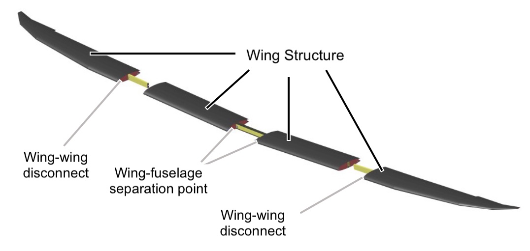
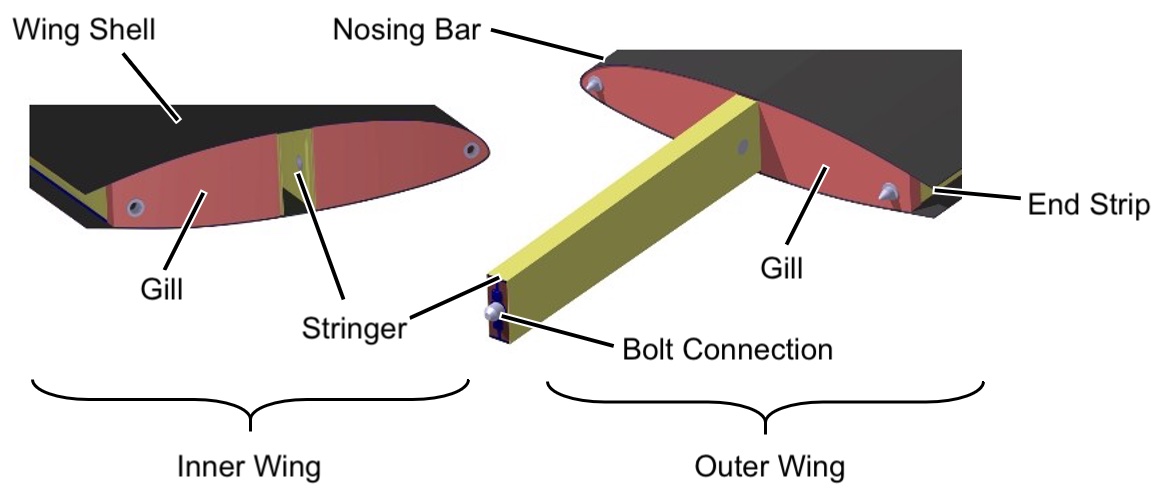
Here, a load-direction-dependent functional separation of the structural components was carried out: Here, the spar consisting of a web and two chords carries the forces in the longitudinal and vertical axis directions as well as the bending moments about the longitudinal axis of the aircraft. The torsional moment is carried by the sandwich shell, whereas the bending moment about the aircraft vertical axis is carried by chords attached to the entire leading and trailing edge. Load transfer at the separation points of outer wing to inner wing and inner wing to fuselage are realized by detachable pin connections, allowing the wing to be disassembled if necessary. A detailed description of the formulas and mechanical calculation of the strength checks is omitted here.
In a previously performed load calculation by IFB, all forces and moments acting on the structure were determined for all maneuver and aircraft configurations to be verified and formatted in tabular form in several Excel files. This data set resolves the internal forces occurring at several hundred support points along the half-span for each load case listed. Before the actual strength check is performed, all load case conditions are imported into the Mathcad worksheet from this interface. Subsequently, the static strength of all considered structural components is compared with the occurring loads in order to verify the minimum safety factors of the predefined component dimensions and thicknesses as specified in the approval regulation CS22. In this process, most of the calculations with all load cases are calculated individually in an iterative process and then the state of the individual structural components with the largest loads and thus the lowest safety factors is output. The evaluation is limited to the output of the safety factors and the verification of the minimum safety factors to be verified. If no local, point-by-point calculation is available, the entire curves of the minimum safety factors along the geometry axis under consideration are created and output in simple graphical representations.
Requirements for the design calculation of the FVA-30 blades
The primary goal of the adjustments to the e-Genius wing design computer is to build on the initial wing load comparisons between e-Genius and FVA-30 from the first part to definitively verify the reusability of the e-Genius wing structure and thus evaluate how to proceed with the FVA-30 wing structure. In addition, based on the results of the design calculation, it is intended in the further course to make minor adjustments to the component thicknesses at critical structural components with safety factors that are too low. This will then allow the production of the FVA-30 wings to begin without having to develop a completely new design, including approval.
In the context of the still ongoing development process on the way to manufacturing the FVA 30 wing structures, a more flexible and comprehensive design of the design calculation was required (e.g. the possibility to quickly and easily allow changes to defined framework conditions or the addition of an effective evaluation of the results for improved internal communication). For this purpose, the existing design calculator from Stuttgart was reused and appropriate adaptations were made to meet our increased requirements. In this way, on the one hand, the self-developed load calculation of our model of the e-Genius and the FVA-30 can be checked for plausibility in comparison to the documents provided by the IFB. On the other hand, a direct comparison of the safety factors of FVA-30 and the already proven strength of the e-Genius can be made possible.
Advancement of the design calculator
In order to make the already developed design computer compatible with our data sets and to enable an additional extension of the functional scope for analytical purposes, far-reaching adaptations of the program flow of the original Mathcad worksheets were necessary. For the time being, no changes were made to the content of the design methodology and calculation of the static strength verification and defined material and geometry properties. For this purpose, rigid program flows related exclusively to the original input data were generalized in order to allow flexible processing of data sets changing in format and scope. On the other hand, the information output after the calculation was extended to enable a more differentiated analysis of the partial results later on. The import of the section loads into the design computer runs very similar to the original with the help of Excel tables, which are exported from the FVA load computer. In the course of further processing, the associated load case key is now also always assigned for identification in order to be able to identify dimensioning load cases later.
A comparison between the different data sets within the Mathcad worksheets themselves was refrained from in order not to complicate the calculation with an overhead required for this, so that the individual documents remain directly usable for the approval. Furthermore, the desired extended graphical evaluation in Mathcad would have been limited and very cumbersome. Therefore, an external program was created for the interactive evaluation of the results. For this purpose, in the Mathcad worksheets, the intermediate results extended by us are instead packed in corresponding CSV files and output collectively for an externally implemented evaluation after completion of the calculation.
For the evaluation and graphical representation of the exported results, we developed a corresponding Matlab application, which allows a centralized and clear analysis of all partial results and, above all, a direct interactive comparison between the results of different data sets.
Evaluation application and comparison of safety factors
In the first step, the developed Matlab application imports the results exported from the Mathcad worksheets and then interprets them in order to present them to the user in an easily understandable interactive graphical form. For the analysis, the user can choose from several representations that visualize a comparison of the results.
After selecting the structural component to be analyzed (e.g. the wing spar web), all loaded data sets can be directly compared in a single plot in order to analyze differences in the safety characteristics of the various aircraft configurations. In doing so, the selection of mapped data sets can be reduced as desired and a detailed info panel can be displayed individually for all calculated data points, explaining, among other things, the load case dimensioning at this support position.
As an example, the following figure shows the curves of the safety factors of the spar web of FVA-30 and e-Genius. For the e-Genius, the strength verification was carried out on the one hand with the load calculation determined by the IFB in Stuttgart and on the other hand with a load calculation prepared by us. Thus, on the one hand, our load calculation can be compared with the load calculation of the IFB (comparison of both e-Genius curves) and, on the other hand, the two curves calculated with our load calculation can be compared from FVA-30 to e-Genius. As can be seen in the figure, the safety factors for the spar web are above the minimum safety factor of 1.5 in all cases. Reinforcement of the spar web of the FVA-30 is therefore not necessary.
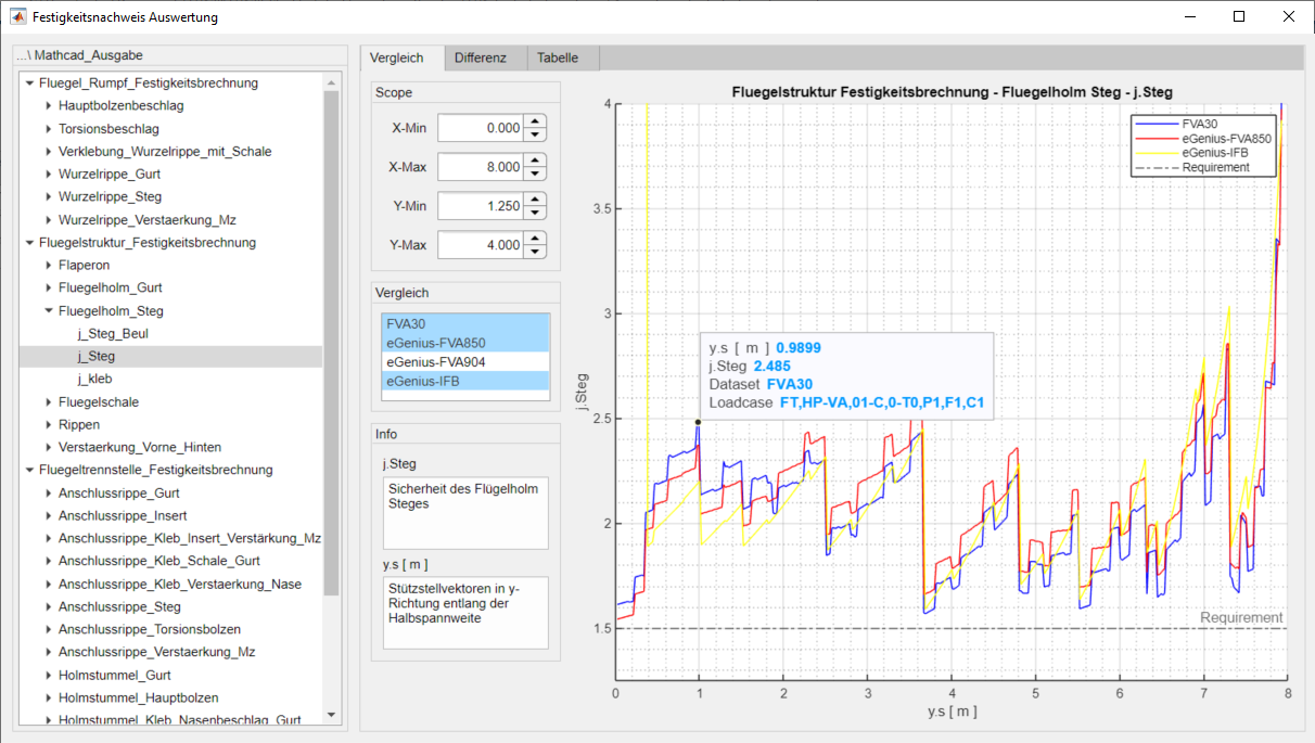
Comparison between the safety factors of selected data sets
In addition, specific differences between two aircraft configurations can be selected and displayed graphically for a more detailed evaluation. This makes it easy to illustrate the quantitative differences and draw differentiated conclusions. As an example, the following figure shows the difference between the safety curves of the FVA-30 and the e-Genius of our load calculation. Here, the sudden change from the positive (safety of the FVA-30 > e-Genius) to the negative (safety of the FVA-30 < e-Genius) at about 2 m is striking. This can be attributed to the different mass distribution of the two aircraft over the half span as a result of the wing pod.
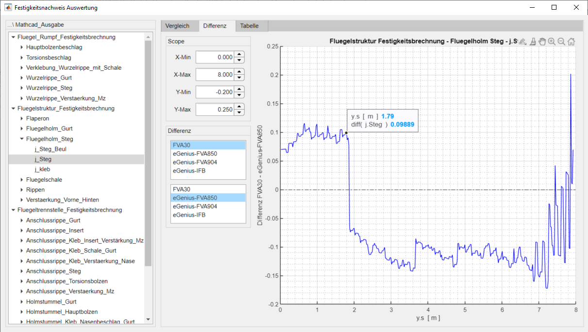
Difference between FVA30 and e-Genius safety curve
Outlook
Using the adapted sash design calculator and the evaluation application created, critical safety factors and critical load cases can now be calculated for all structural components and compared with the prescribed minimum safety factors. This means that a test and evaluation of the structural components can now be carried out and critical areas identified. If the safety factors are not sufficiently high, targeted strengthening measures can then be carried out in the Mathcad design calculator by locally adjusting component dimensions, such as wall thickness. Together with the load calculator, there is now an automated tool chain from model input to the designed wing structure. The design tools for the fuselage and the empennage are now also integrated into this tool chain. If the safety factors of all structural components are sufficiently high, production of the wings can then begin. To do this, laminate layout plans must be drawn up for all components, production materials selected and the actual production sequence planned.