Published: 13.06.2020 by FVA
The system architecture of the FVA-30 is a continuous evolution driven by the requirements of the various components of the aircraft. Important for the design is not only the electrical powertrain, but also mechanical assemblies such as the trim, avionics and lighting of the aircraft. In order to meet all requirements, it is important to know and implement the different interfaces early on so that if a change is made, the impact on the system architecture can be traced back.
In addition to the development-related design, the safety of the aircraft must always come first. The system architecture should therefore also offer the possibility of tracing back errors systematically.
Selection of the control unit
In order to create a basis for the evaluation and design, a schematic sketch of the system was created. This contains all necessary electrical components and their connection to each other. The concrete selection of easily available components such as resistors, LEDs and various signal lines was placed in the background. Priority was given to the selection of components with complex interfaces such as the control unit. The requirements for the control unit were derived from the system plan and forwarded to potential companies.
The following table gives an overview of the control unit requirements:
| ID | ORIGIN | REQUIREMENT | VALUE |
|---|---|---|---|
| 1 | Safety | Separate CAN busses | 3 |
| 2 | System Integration | I/O ports | 30 |
| 3 | System Integration | Analog inputs | 12 |
| 4 | System Integration | Analog outputs | 8 |
| 5 | System Integration | Input voltage | 12V |
| 6 | Evaluation | Logging of flight data | - |
| 7 | Flight Mechanics | Weight | max. 1.5 kg |
After narrowing down the requirements, we were able to contact several companies and obtain both advice and quotes. In the end, we were convinced by the Baseline control unit from Speedgoat, which could be optimally adapted to our needs thanks to the flexibly assignable I/O extensions.
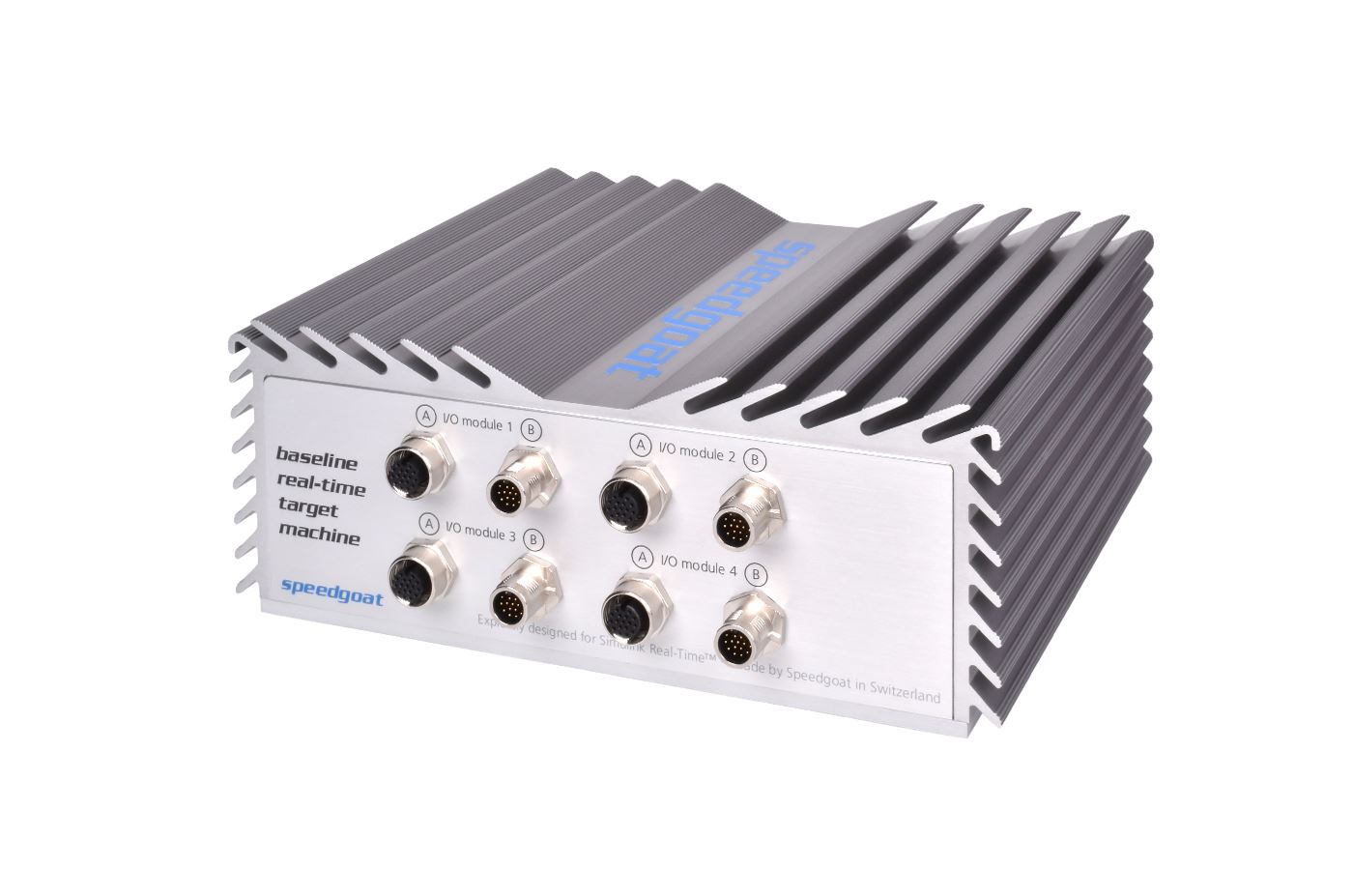
Speedgoat Baseline real-time target machine
The Baseline controller has an Intel Atom CPU as the main processing unit, which has an extended temperature range of -40 °C to 85 °C. The controller is powered by 9-36 VDC and consumes 36W. The controller is powered with 9-36 VDC and consumes 36W. The weight is 1.1 kg in our desired configuration. For logging purposes a 256GB SSD is installed, which replaces the standard hard disk with a size of 32GB. Furthermore the expansion modules IO397 (3 times) and IO614 (1 time) are installed. So the controller has 4 seperate CAN ports, 42 IO ports (3.3V/5V), 12 analog inputs and 12 analog outputs.
As a further plus, we were able to win the company Speedgoat as a new project partner. Especially the familiarization with the complex software, long-term support and changes to the hardware equipment are thus made easier for us.
Design & development of the display unit
To monitor the technical parameters of the powertrain, a display unit consisting of two independent elements is planned – a group of indicator lights and a digital display unit.
The indicator lights are triggered directly by the corresponding control units in which a malfunction first becomes perceptible – for example, the exceeding of a limit value at a measured value detected by that control unit.
The digital display unit consists of a single board computer with corresponding carrier board, monitor, log data memory and input devices. The monitor and input devices are hardware taken from SteFly glider computers. The single-board computer (model name “Apalis iMX6 Quad 2GB Industrial Temperature”) is a device from Toradex, a manufacturer of single-board computers, whose devices of the selected product family are already used in the aerospace industry, according to their own information. According to the manufacturer, the single-board computer is approved for a temperature range of -40°C to +85°C and has been tested for resistance to vibration in accordance with standard EN 60068-2-6 and for resistance to shock (50g / 20ms) in accordance with EN 60068-2-27. The log data storage is a commercially available SSD in mSATA format.
The individual elements are connected via the carrier board (also from Toradex; model name “Ixora Carrier Board V1.2A”). The carrier board contains an mSATA connector for the log data storage, LVDS for the monitor, USB for the input device, down converters for the power supply of the individual elements, as well as a CAN bus transceiver via which the single-board computer receives the parameters from the corresponding control units.
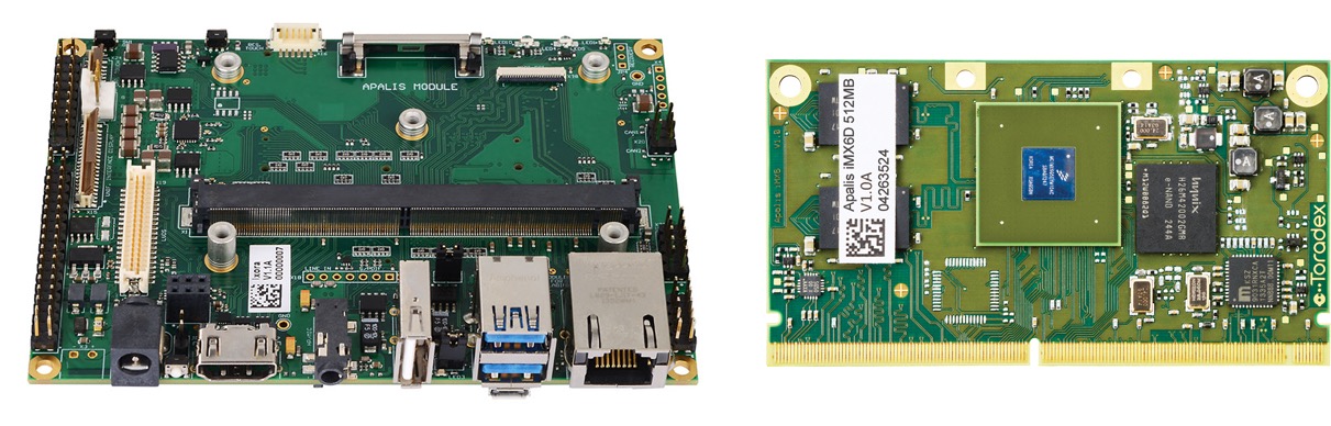
Toradex Carrier Board (left) and single-board computer Apalis iMX6 (right)
The basic structure of the software used is comparable to the structure of the software used in OpenVario-based glider computers. It is an operating system based on OpenEmbedded, which forms the firmware of the single board computer in a hardware specific version and together with application specific software. The communication with the hardware (CAN bus – receiver, control for monitor, input device and protocol data memory) as well as corresponding functions (display of text and two-dimensional geometric shapes, processing of input from the input device and CAN bus) are provided to the specially written software by the operating system.
The specially developed software has the task of processing the received parameters into a readable graphic form. The software reads the parameters received via CAN bus and converts them into corresponding geometric shapes and lettering, which are to represent the displayed parameters. It takes into account which parameters are to be displayed at the moment – the user has the possibility to choose a part of the parameters to be displayed (important parameters, such as the battery content, are always displayed). Optionally, the parameters are saved to the log data memory. The set of geometric shapes and lettering is “passed” back to the operating system for display.
Outlook
In the coming months, we will finalize the design and component selection and focus on system integration, as well as the tests postponed due to external circumstances (Covid-19). Right at the beginning of the new semester, the motor test runs at the Institute for Electrical Machines at RWTH Aachen University are planned. Subsequently, after completion of the planning for the “Ironbird” (complete powertrain assembly for realistic ground tests), the same is to be built in our workshop. Our subsystems such as the motor/inverter system or the display unit will then be integrated there and tested in consultation with the German FAA.