Published: 2.01.2020 by Marvin Garbade
A particular challenge in the development of our battery pack is the design of a fail-safe thermal management system that can mitigate temperature rise during start & climb and prevent undercooling during 4-5 h of range-extender-powered cruise flight at up to 3000 m, where batteries need to be recharged and remain operable, e.g. for a go-around. Therefore, a passive cooling approach based on a phase change material compound (paraffin encapsulated in solid structure, e.g. a porous matrix of expanded graphite or HDPE with a thermally conductive additive) was laid out, that effectively raises the pack’s thermal inertia, provides structural support (less overhead on cell fixations) and allows the pack to be fully sealed. This approach overcomes major deficits of conventional cooling techniques: both liquid and air cooling would not allow a significantly denser cell packaging (currently: 3.6 mm distance between cells), hence having higher volume demands regardless of their cooling power due to additional components outside the pack (e.g. air inlet, radiator, tubes, heat exchanger) while volume is our toughest constraint as available installation space must also fit both range extender and converter. In addition, the proven protection against fire propagation offers a decisive advantage over conventional cooling. As far as weight is concerned, the additional weight of the PCM compared to a lighter (forced) air cooling does also come as a benefit since the battery is used to stabilize our center of gravity that is shifted backwards due to our tail-integrated propulsion.
We previously covered the construction of our first test module as well as flight profile tests performed with it, while the module already integrates all relevant components of the later battery pack, that will comprise 12 of such modules in series. The component selection for the test system was, however, partly based on availability and differs from the final design. Particularly, the PCM compound used – a donation by the Fraunhofer Institute for Structural Durability and System Reliability (LBF) – does not suit our requirements with a melting point of 25 °C, as the paraffin encapsulated in the structure must not be melted at (reasonable) ground temperatures since the phase change is to be triggered by battery heating. The CAD-design and preceding material demand estimations were, however, based on the product PCC48-1000 by AllCell Technologies that provides a useful reference for what is possible. These material properties shall be analyzed more closely in conjunction with the power loss of our battery cell, covering different flight scenarios. By studying heat loss and transient heat transfer, we are able to optimize material selection (melting point) and composition (heat capacity ⇔ thermal conductivity).
The battery module consists of 12 serially connected submodules, each being a string of 5 parallel connected cells in a PCM cell holder as shown below.
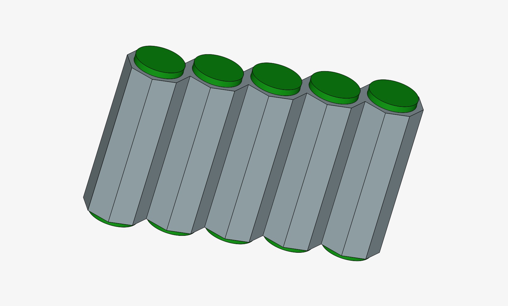
Submodule with five parallel connected cells in PCM cell holder
Each cell is surrounded by a 1.8 mm thick PCM wall (at the narrowest point), hence there is a distance of 3.6 mm between the cells. The thermal connection between cell and PCM is established by tightly fitting the cells in the corresponding sockets and applying thermal grease for improved conductivity.
Simulation Strategy & Assumptions
For the transient heat analysis, the free CAE software SimScale is used. A single battery cell enclosed in the corresponding PCM shell is imported as shown below.
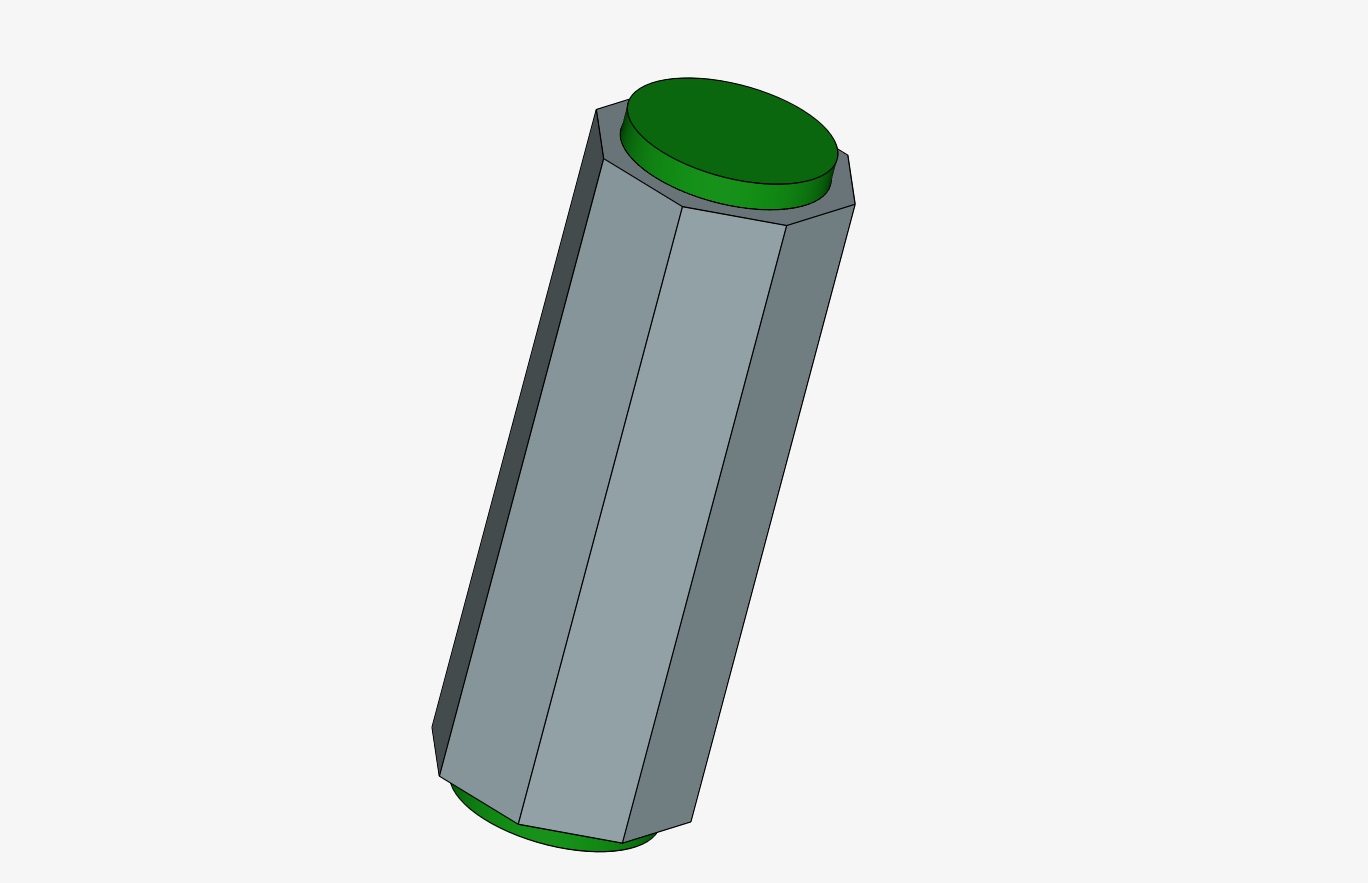
Single cell in PCM shell, 1.8 mm wall thickness (narrowest point)
The simulation setup is completely adiabatic, i.e. all power losses of the cell are transferred into sensible heat of the battery and PCM as well as latent heat of the phase change. Therefore, this scenario gives a conservative estimate of the thermal behavior since the strong heat flow into the copper connectors and heat up of other elements in the module assembly is neglected.
For simplicity, thermal conductivity is implemented as isotropic, using values for radial conductivity within the cell (which is much lower than axial conductivity) and pessimistic conductivity values from the PCM data sheet.
The phase change is transferred into a sensible heat scenario, where for the given melting range of 45° C – 50 °C, the PCM heat capacity is replaced by the latent heat capacity divided over that temperature interval.
The battery is assumed to produce a uniform volume heat flow corresponding to the profile simulated. Power loss is directly estimated from current and voltage data, taking the cell’s state-of-charge (SOC)-dependent open circuit voltage (OCV) as a reference:

Input Profiles
The same profiles as tested previously on the whole module are used, i.e. constant power profiles for the 4 cases
- Full-power battery-electric profile (ELECTRIC-FULL)
- Reduced climb rate battery-electric profile (ELECTRIC-REDUCED)
- Range-extender-supported profile (REX)
- Emergent redundancy profile (EMERGENCY)
The data from the previous tests is used where the measured pack current is divided equally over the 5 parallel cells and cell voltages are averaged. The measured power profiles for the above mentioned 4 cases are again summarized in following tables, here mapped on single-cell level.
ELECTRIC-FULL
| Start | Climb | Cruise | |
|---|---|---|---|
| Power | 65.5 W | 47.57 W | 10.22 W |
| Duration | 90 s | 300 s | 1108 s |
ELECTRIC-REDUCED
| Start | Climb | Cruise | |
|---|---|---|---|
| Power | 65.5 W | 34.67 W | 10.22 W |
| Duration | 90 s | 634 s | 389 s |
REX
| Start | Climb | Cruise | |
|---|---|---|---|
| Power | 48.17 W | 30.17 W | - |
| Duration | 90 s | 891 s | - |
EMERGENCY
| Start | Climb | Cruise | |
|---|---|---|---|
| Power | 131 W | 83.3 W | 20.4 W |
| Duration | 35 s | 160 s | 764 s |
Material Parameters
Following material parameters were extracted from the data sheet of PCC48-1000 and implemented according to the above-described approach.
| Melting Range | 45 °C – 50 °C |
| Density | 890 kg/m3 |
| Thermal Conductivity (here isotropic) | 10 W/mK |
| Latent Heat | 180000 J/kg |
| Specific Heat Solid | 1820 J/kgK |
| Specific Heat Liquid | 1960 J/kgK |
Overall, the mass of PCM per cell amounts to 7.27 g according to our CAD-draft. That results in a latent heat capacity of 1308.6 J = 0.3635 Wh. Further heat loss will result in a temperature increase of battery and PCM. The battery cell’s specific heat capacity has been assumed as 950 J/kgK based on literature values for comparable 18650 cells.
For the thermal conductivity within the cell, literature values have been studied and a value of 0.2 W/mK seemed to be a valid conservative estimate for an 18650 high-energy NMC cell, e.g. according to this NASA report (2018).
All profiles start at an ambient temperature of 20 °C.
Simulation Results
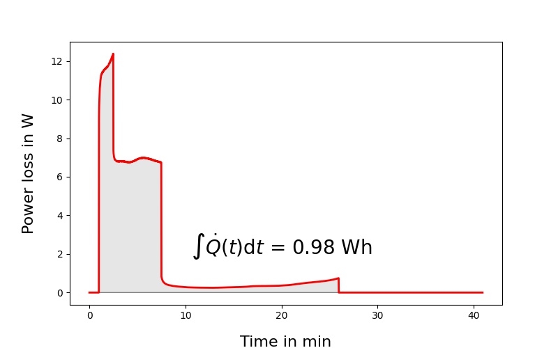
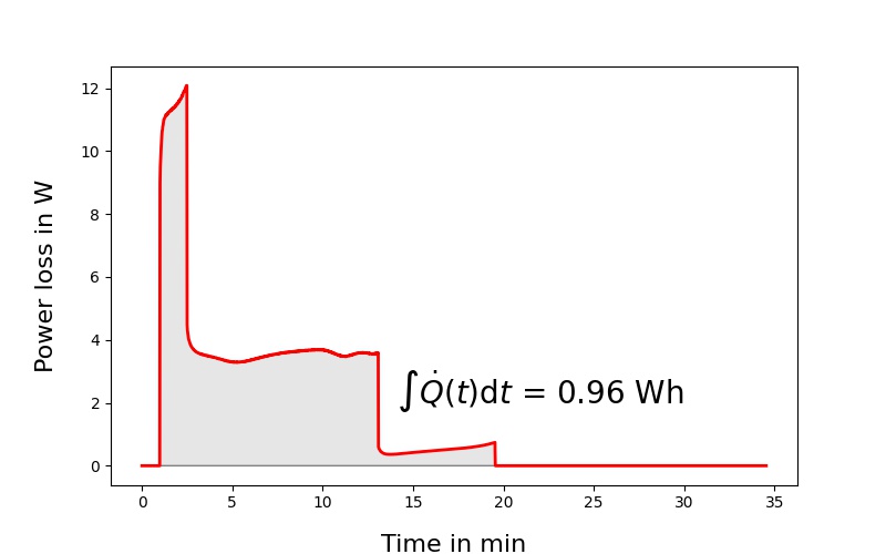
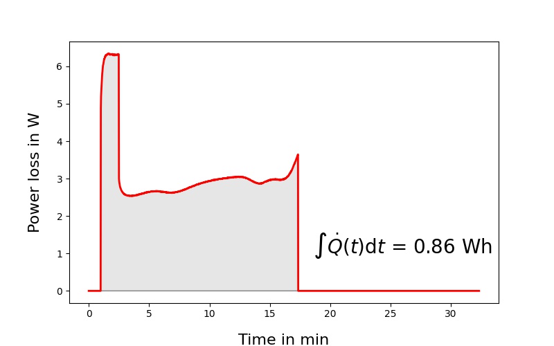
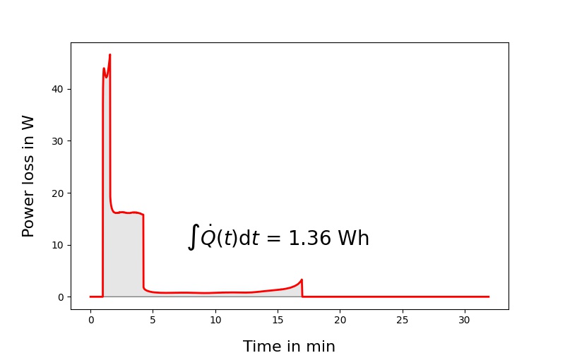
For each profile, two results are shown: the left side depicts power loss over time with the integral being the amount of heat generated while on the right side, the transient temperature simulation can be viewed.
ELECTRIC-FULL
ELECTRIC-REDUCED
REX
EMERGENCY
Considering the thermal mass of battery and PCM in addition to the phase change energy, the theoretical thermal capacity for a temperature rise of \Delta T = 40 °C (e.g. starting from 20 °C ground temperature and allowing a maximum temperature of 60 °C) would be 1.01 Wh, which is sufficient for all profiles except for the emergency case. The latter needs to receive additional considerations in upcoming tests.
However, it is to note that all of the above profiles exceed the actual design targets, i.e. a fully-electric flight with start, 1000 m climb and 15 minutes cruise flight (phase I) or a battery-assisted start with range extender to a maximum altitude of 3000 m (but not necessarily at the tested high climb rate of 3.4 m/s), where the range extender covers the constant cruise power (phase II).
Concerning the PCM compound, the simulations suggest that the properties of PCC48-1000 would indeed suffice both in terms of thermal capacity and conductivity. Even higher paraffin loadings seem possible as thermal conductivity plays a minor role due to the thin structure. Regarding the optimal melting point, however, a slight reduction, e.g. to 42 – 45 °C, might be beneficial as the melting process is only triggered when the battery cell has already reached a (significantly) higher temperature.