Published: 16.12.2019 by Benjamin Kelm
For the FVA-30, the wing geometry and a large part of the fuselage are identical to the e-Genius. However, there are major deviations in the mass distribution for the components associated with the tail unit, the propulsion system and the power supply. This results in a center of gravity shift that must be corrected to ensure flight mechanical stability.
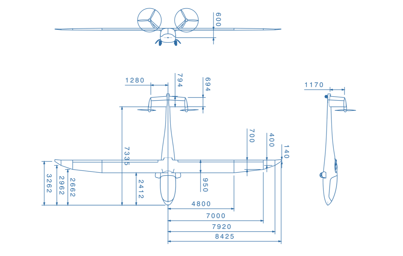
Preliminary aircraft geometry of the FVA-30 (as of 2019).
Neutral point shift due to hull influence
In addition, the fuselage contributes to an aircraft neutral point displacement. In order to be able to represent this influence, the fuselage is included in the AVL geometry model as a lift surface by means of a projection into the x-y plane (cf. figure below). Numerical comparisons with and without the fuselage show that this methodology does indeed represent the neutral point displacement due to the fuselage. However, the influence is slightly overestimated (20%).
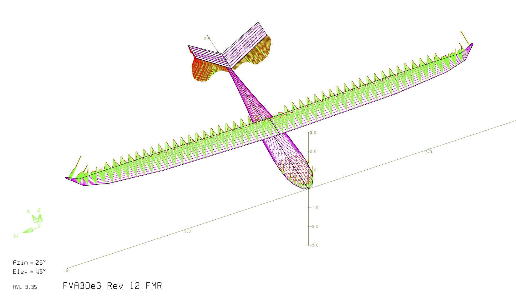
AVL geometry view with lift distributions for the flight condition “take-off on landing approach, foremost center of gravity with max. thrust”, fuselage approximated as a flat plate (cruciform fuselage)
Necessity of a wing displacement
To ensure static stability, the aircraft neutral point must be located behind the most rearward C.G. position. In addition, a static margin of 5% should be maintained. However, this cannot be maintained with the expected center of gravity limits. Therefore, in order to meet this stability requirement, either the aftmost C.G. boundary must be moved forward (1) or the aircraft neutral point must be moved aft (2).
(1) Shifting the rear center of gravity boundary forward
- Fore fuselage extension: – Difficulties with contour continuity & construction effort
- Raising the minimum payload or trim weights: – Reserved as a final adjustment option
(2) Shifting the aircraft neutral point backward Modification of the tail unit:
- Increase of the tail surface:
- Simple implementation (tail unit still to be built) – Weight, resistance, low efficiency
- Modification of the tail extension:
- Simple implementation (tail unit still to be built) – Larger lever arms for thrust moment, weight, low efficiency.
Wing adjustments:
- Geometry changes: not possible, as wings are to be completely taken over by the e-Genius
- Change of the wing attachment point:
- Great effectiveness, only about 30% of the mass (wing) is displaced with.
- Implementable with relatively little effort.
Due to the relatively low effort to move the wing attachment to the fuselage and the high effectiveness, this method is preferred to the others.
Optimization Methodology
With the gained degree of freedom of the wing root displacement, an optimization calculation for the optimal, i.e. smallest empennage, which nevertheless fulfills the requirements for stability and controllability, was performed. This is only possible numerically (MATLAB, FVA-30 Flight Mechanical Design Computer), since a large number of dependencies (e.g. pitching moments dependent on thrust and tailplane height) can only be solved iteratively.
In the calculator, the C.G. position is first adjusted for a possible wing root displacement range of +/- 200mm, based on the current wing position, since the masses of the tanks/wingpods are always also displaced with a displacement of the wing root. Further, for each optional wing root displacement point (step size 1mm) a minimum control surface is calculated and stored according to the flight mechanical requirements for longitudinal and lateral movement. Maximum rudder deflections to be controlled, which result from aerodynamic considerations at the tail unit, are also included in the calculation. The results of the optimization calculation are shown in the following figure. It can be clearly seen that a minimum for a wing root displacement of 136 mm emerges. The legend lists the individual requirements according to which the empennage areas are calculated, whereby the total area of the empennage is to be minimized.
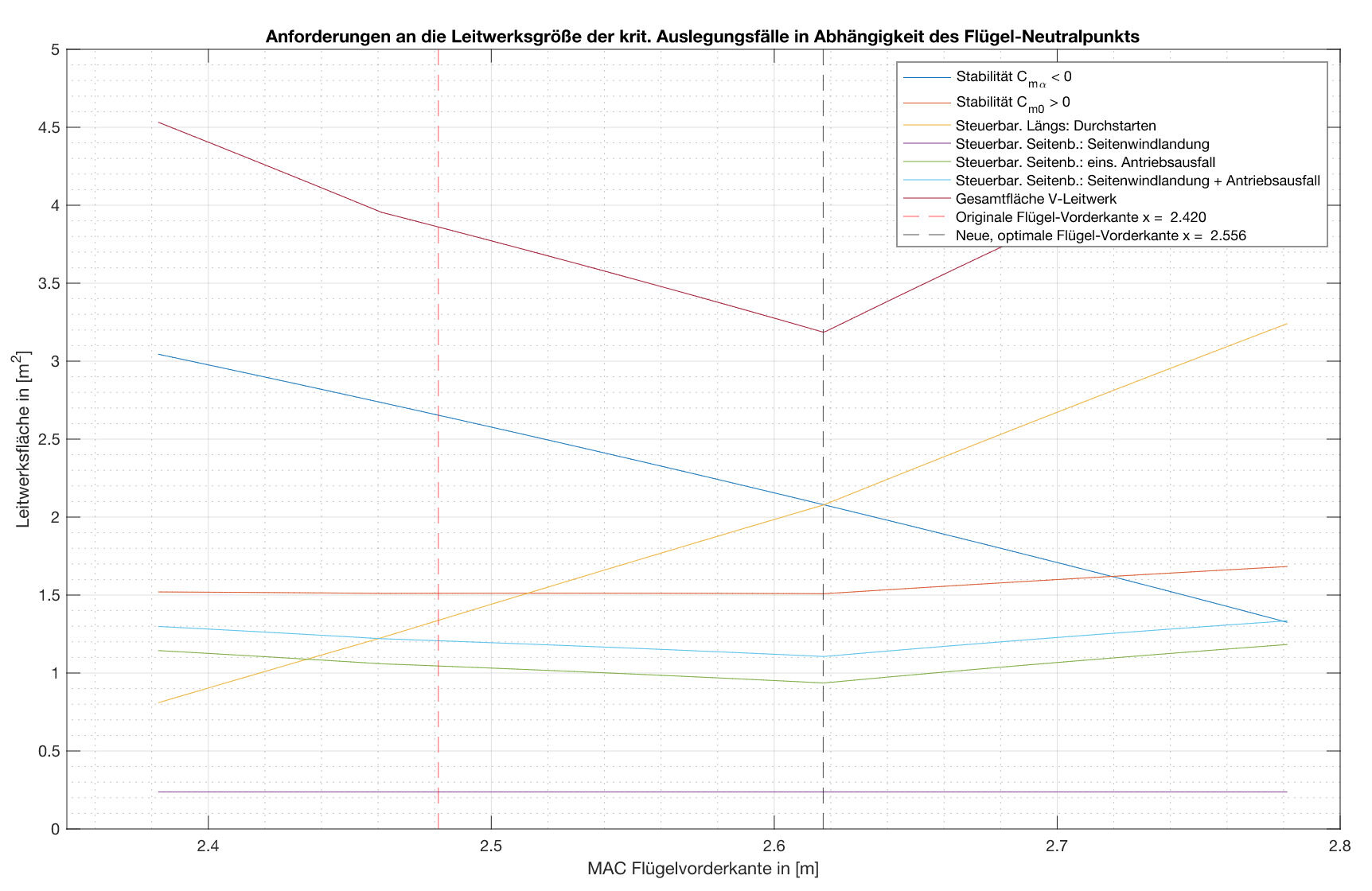
Change in the size of the empennage as a result of the wing root displacement
After considering various other factors, such as the modifiability of the original shape, belt positions and tail wheel loads, it was finally decided to shift the wing attachment by 120 mm. However, since it is difficult to shift the wheel well due to restrictions in the installation space, the planned wing root shift results in a slightly increased tail wheel load, which must be taken into account in the tail wheel design.