Published: 3.12.2019 by Marvin Garbade
In preparation for the final construction of battery pack and housing, we ran first experiments concerning fire protection in the unlikely case of a thermal runaway . For this purpose, first tests focused on the GRP panels placed between each block of parallel connected cells (cf. test module) while the effect of additional fire protection paint was to be investigated. In the second test series, the effects of a provoked cell explosion of a fully charged cell on neighboring, parallel connected cells in a PCM block were studied.
Test Series 1: GRP Panels
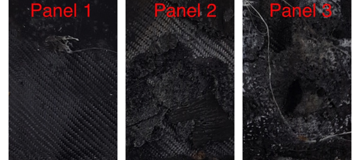
Three GRP panels in different configurations were tested. Panel 1 had no protection, panel 2 had one layer of fire protection paint and panel 3 had two layers. The panels were individually clamped in a vice and the coated side was brought to 600-800 °C with a burner. This temperature corresponds approximately to the maximum temperature generated by a cell fire. On the uncoated side, the temperature was measured using a temperature sensor pressed between the insulation and the GRP.
The resin in panel 1 caught fire after only 4 seconds, resulting in complete delamination. A cell-damaging temperature of 60°C was reached after 8 seconds on the side facing away from the heat. The temperature then continued to rise rapidly until the test was stopped after 20 seconds. Plate 2, on the other hand, caught fire only after 9 seconds, at about the same time the opposite side reached 60°C. The test was stopped after 12 seconds. Panel 3 caught fire only after more than 30 seconds. The opposite side reached 60°C after about 12 seconds. The test was stopped after 90 seconds.
Based on studies of reference abuse tests, it is expectable that the effective burning time of an 18650 lithium ion cell is at most 4 seconds. Due to heat accumulation and the sudden high pressure, the test temperature can be maintained for 6-7 seconds, though. The aim of our design is to prevent permanent damage to the adjacent parallel connection or a firing of the resin during this time. This can be demonstrably achieved by coating the GRP panels with one layer of fire protection varnish as the critical damage can only occur after 9 seconds here.
Test Series 2: PCM / Battery Abuse
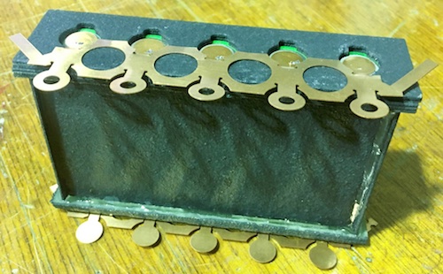
For the thermal runaway test, a block of five parallel cells in a form of phase change material as used in our test module was constructed. The cells were soldered with a 0.3 mm copper sheet per pole. The cell holder consists of lasered 1 mm GRP plates. On the top and bottom side, four of these plates were glued on top of each other. The outside of the cell holder and the side panels were also provided with two layers of fire protection paint on the inside. Afterwards the pack was charged so that the energy content of the cells is at a maximum. The cell voltage was 4.15 V. The macro cell was fixed in a holder open in all directions.
In the first two tests, the positive terminals of two cells were drilled through from above. The cell produced a large fire fountain of 4 s followed by a slight afterburning of 27 s. Similarly, the second triggered cell produced a 5 s flash with a subsequent 46 s light fire. In both cases, the copper sheet was cut through and fire protection paint on the outer walls has triggered in the area of the burnt cells. No adjacent cell was affected and a voltages of 4.13 V (test 1) and 4.11 V (test 2) were measured.
The distance between the cells and the PCM successfully prevented fire propagation to the adjacent cells. Since the copper sheet was cut in both tests, the internal cell short circuit did not affect the other cells for long. The PCM was slightly damaged towards the edge of the respective cell, but still largely intact.
A large part of the heat was emitted directly to the surroundings by the large flame. By piercing the cell into the positive pole, it was not possible to determine whether the flames came from the pressure relief valve in the positive pole or from the hole drilled. Therefore, the cells should be embedded into a housing with covered poles and pierced laterally in the following experiment.
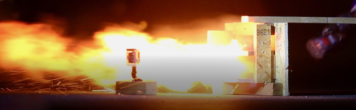
The macro cell was reprocessed by replacing the destroyed cells and the copper sheet. Both the PCM and the cell holder were reused. A new frame was constructed so that there is a wooden wall about 10 mm above and below the macrocell. In addition, two side walls and a back wall were added, so that the flames can only spread in one direction, so that more impact of the flames on the neighbouring cells is expected. The macro cell was fully charged and preheated to 45 °C so that the PCM phase change cooling is effectively prevented. One cell was now drilled through laterally with a screw. There was immediately a jet of flame, which spread for 1-2 s from the front of the opening of the test setup over 1 m. The flames extinguished by themselves after 8 seconds. No other cell was affected. The fire protection paint on the outer wall has triggered again in the area of the destroyed cell. A part of the copper sheet at the positive pole was catapulted about half a meter.
By drilling into the side of the cell there was a shorter but larger flame. In addition, the flame was directed forward through the wooden panels. This time the flame escaped downwards as well as upwards. No other cell was damaged. The same PCM between cell 3 and 4 thus successfully prevented the fire from spreading to the neighboring cell twice in a row.
In the wooden plates above and below the destroyed cell there were traces of burn-in, some up to 3 mm deep. Therefore, in the next test, a 1 mm thick GRP panel with fire protection varnish should be used instead of the wooden panel to see how much it will be damaged.
This time the damage to the macro cell was greater. The side walls and the PCM were partially burnt near the destroyed cell. Also the heat shrink tube of cell 2 was slightly damaged towards the pole. However, no other cell was ignited. Because of the presumably longer smouldering fire of the GRP plates, there is now the consideration to use a fire-retardant resin system.
The completely detached and desoldered copper sheet shows that it might be useful to repeat the test with welded copper sheet. It is also possible to fix the copper sheet to the GRP plate with a heat-resistant adhesive to prevent it from coming off in a fire and causing a possible short circuit in the battery.
On the macro cell facing side of the upper GRP panel of the enclosure the fire protection paint showed burn marks, but was hardly damaged and withstood the flames well. Flames have escaped at the narrow edges of the enclosure panels. It is recommended to seal the enclosure better in the future.
Conclusions
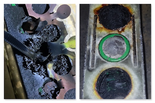
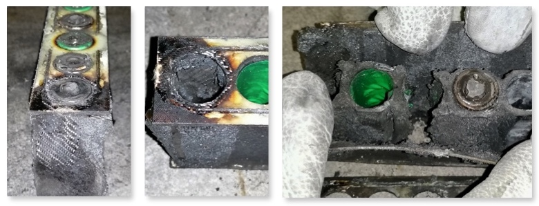
PCM – After the experiments, the macrocell was dismantled and the inner workings were examined. The PCM inside the macrocell is partially heavily damaged around the ignited cells. On the undamaged cells, however, it was still almost intact. The PCM was partially burnt on the surface and in one case it partially penetrated to the GRP plate. The matrix of the PCM melted and was deformed by the heat. Our fear that the paraffin inside the PCM compound could accelerate the fire was not confirmed. Instead, the PCM seems to thermally isolate the neighboring cells from the burning cells and absorb some of the energy. Further testing without the PCM could be used in the future to further investigate this suspicion.
GRP sheets – In the last attempt the lateral GRP sheets have started to smoulder. Under certain circumstances, it may therefore make sense to test a self-extinguishing resin system in the future. GRP panels of 1 mm thickness, which are coated with fire protection varnish, seem to work well as a battery housing so far. At a later date, however, a more extensive test will be carried out with a partial model of the final housing design.
Copper sheet – As the copper sheet has usually become detached during the tests due to the heat, future tests should be carried out with welded contacts.