Published: 10.03.2020 by FVA
After working out a comprehensive selection of cooling concepts, the choice fell on a conventional concept based on a finned radiator typical of the automotive industry. This essentially guaranteed a customized selection of the radiator and the elimination of a costly and computationally intensive design for an in-house construction. We also decided to completely separate the cooling of the two powertrains in order to preserve the redundancy developed so far and thus also the reliability. The entire design process took place in consideration of JAR 22, as well as the Provisional Guideline for the Installation of Electric Motors in Powered Sailplanes.
System Overview
Essentially, the cooling of a drive train consists of two spatially separated circuits. This separation was made due to the large spatial distance between the motor and the inverter. A compound of the systems was characterized in the Weight & Balance by a negative effect on the center of gravity and the total weight, which was mainly due to the weight of the lines and the additional cooling liquid. The engine’s cooling system is located in the engine nacelles, while the inverter’s system is located in the rear of the airframe. In addition to identical radiators and pumps, both systems have a number of sensors and an expansion tank that also serves as a refill nozzle.
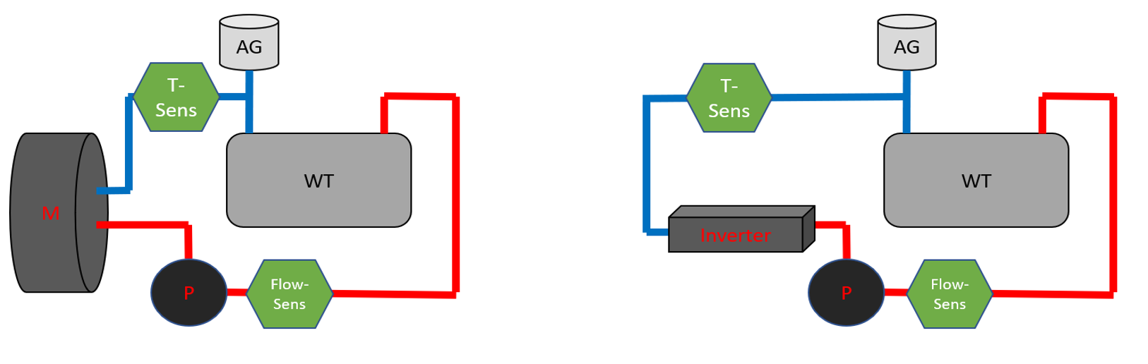
Preliminary system overview of powertrain cooling
Radiator
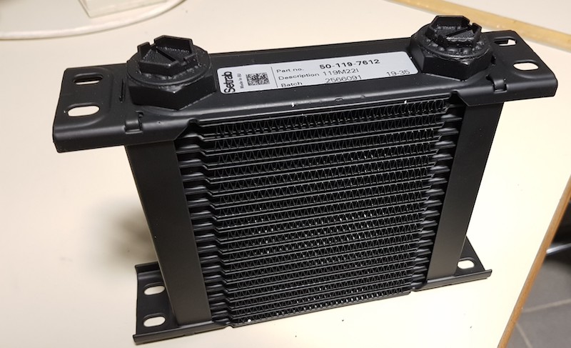
The radiator should be designed in such a way that it would also be able to permanently dissipate the take-off power loss of approx. 2kW at an incident flow of approx. 30 m/s. This flow is to be expected in the direct wake of the propeller during takeoff. The preliminary choice was a fin-type oil cooler from Setrab. The main advantages of this design are its low weight and comparatively low pressure loss. Based on the data sheets provided by this company, it was possible to verify sufficient cooling of the components concerned, given the flow rate required in the data sheets for the inverter and motor. The two cooling circuits have the same radiator model, as the requirements, especially the power loss, are very similar.
Coolant Pump
This selection of the coolant pump turned out to be quite difficult, since the selection in the required performance class is small. The pressure loss of the motor alone is about 0.9 bar at 7l/min. On top of that, the losses in the pipes and the radiator add up to a total loss of 1.3 bar (0.9 bar in the inverter circuit) at 7l/min. One of the few pumps that provides such a performance at low weight is the GRIPumps INTG3 series.
Sensors
Electronic control and monitoring of the cooling circuits is essential for safe, efficient operation, as well as appropriate integration into the operating concept of the FVA-30. For this reason, we install a temperature sensor and a flow sensor. The temperature sensor is installed at the inlet of the component to be cooled. This allows us to monitor the inlet temperature, which is limited to a maximum in the component data sheet, and to protect the component from overheating. In addition, the output of the coolant pump can be dynamically controlled, thus saving energy. The flow sensor, on the other hand, is installed directly behind the pump. This enables verification of the control and early detection of leakage or failure of the pump.
Coolant and hoses
A conventional mixture of water and antifreeze based on ethylene glycol is particularly suitable as a coolant for our purposes. These coolants are not only widely available, they also have a high heat capacity, which significantly delays heating. Also, the degree of antifreeze is freely adjustable and mixture widely available in the retail market.
Therefore, resistant hoses and seals can also be easily found. In this case, we chose special pressure-resistant hoses and seals made of EPDM material, which is particularly tough and resistant to ethylene glycol.
Air Inlet
The introduction of cooling air into the two cooling circuits is still under development at the moment. In the engine cooling circuit, for example, only one NACA air inlet is expected to be installed in the surface of the engine nacelle, since air flow is present here as soon as power loss is produced (propeller rotates).
The air supply to the inverter circuit, on the other hand, is somewhat more complex, since flow is only present here as soon as the aircraft starts moving. For this reason, a fan is to be installed here, which is currently being designed. Tests are still necessary to determine the pressure loss of the air flow through the radiator.
Outlook
The two circuits of a drive train are currently under construction. Initial experience is also being gained with the sensor system and a preliminary control unit is being developed on the basis of a development board. This is to be calibrated in the course of the first tests and will take over control during the engine tests scheduled for next year. First, however, the circuits will be subjected to pressure and leakage tests to prevent failure and consequent failure of the tests on the engine test stand. During this phase, the component to be cooled is not connected to the system, but is simulated by heating the cooling water. The aim is to gain experience in the use of this system and to identify and eliminate possible faults and weak points at an early stage.
The preliminary goal is to verify the design by simulating the performance profiles of the FVA-30 during the engine tests and, if necessary, to optimize the system.